190-00303-A3
GSB 15 Installation Manual
Rev. 3
Page 3-1
3 INSTALLATION PROCEDURE
3.1 Wiring Harness Installation
Allow adequate space for installation of cables and connectors. The installer shall supply and fabricate all
of the cables. All electrical connections are made through a single connector.
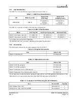
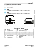
defines the electrical characteristics of all input and output signals. Required connectors and
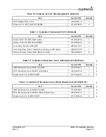
associated hardware are provided in the connector kit (
).
CAUTION
Do not apply power to the unit until after the rear connector is completely seated.
Connecting the unit while power is applied may cause damage to the device, and to other
LRUs that are connected to the data lines.
NOTE
For data transfer installations, the ring terminal is required. If used, torque the ring
terminal s
crew to 4-6 lbf-in.
3.2 Equipment Mounting
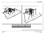
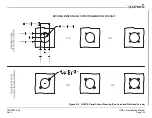
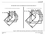
For final installation and assembly, refer to the outline and installation drawings shown in
this manual.
1. Assemble connector per instructions in
.
2. Install the unit from the back side of the desired installation surface with the circular surface
protruding through the hole.
3. Attach the unit to the installation surface using a minimum of two screws (oriented diagonally).
Rotational orientation of the unit within the mounting location is at the installer’s discretion. The
recommended screw torque is 4-6 lbf-in.
4. Attach the cable harness to the connector, paying attention to the keying and latching features of
the connector.
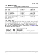
5. If using mounting kit 011-05043-00 or 011-05043-01, mount adapter plate to desired mounting
surface using specified screws (see
) and attach unit to adapter plate using included
screws.
CAUTION
Be careful to not damage the unit or connector during installation. Avoid over-torquing
mounting screws.
NOTE
For rear unit (011-04937-00) installations, ensure the portion of the panel that mates to
the GSB 15 is electrically conductive to ensure proper grounding.
3.2.1 Unit Replacement
Make sure that power is removed before removing the GSB 15.


