


190-00303-A3
GSB 15 Installation Manual
Rev. 3
Page 2-2
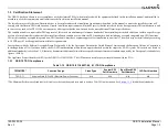
2.5 Cabling and Wiring
Wiring must be installed in accordance with AC 43.13-1B Chapter 11, Sections 8 through 13. The
following issues must be addressed:
• Do not expose cabling and wiring to chafing
• Do not route cabling and wiring harnesses near flight cables
• Do not route cabling and wiring near high-energy sources. (e.g. DC motors, high heat sources)
• Wiring indicated as shielded in Appendix B must be shielded
• Pigtail lengths must be less than 2.5 inches.
• Use 20 or 22 AWG for power and ground wires, 25 ft max.
2.6 Shielding and Electrical Bonding Considerations
Electrical equipment, supporting brackets, and racks must be electrically bonded to the aircraft’s main
structure or a designated aircraft groundplane. Refer to the following documents for applicable bonding
techniques:
• AC 43.13-1B CHG 1, "Acceptable Methods, Techniques, and Practices - Aircraft Inspection and
Repair", Chapter 11, "Aircraft Electrical Systems"
• SAE ARP 1870A, "Aerospace Systems Electrical Bonding and Grounding for Electromagnetic
Compatibility and Safety"
• A bonding procedure developed and supplied by the aircraft manufacturer (if available)
The electrical bond must achieve direct current (DC) resistance less than or equal to 2.5 milliohms to local
structure where the equipment is mounted. Compliance must be verified by inspection using a calibrated
milliohm meter.
2.7 Cooling Requirements or Considerations
The GSB 15 has no cooling requirements or considerations. Forced air cooling will reduce the internal
temperature of the unit and prolong the life of the product.
The GSB 15 is equipped with over-temperature detection that may reduce output current to 1.5A (max) .
After the device has cooled, normal output current 3A (max) will resume.