GPSMAP 192C Owner’s Manual
99
A
PPENDIX
>
C
ONNECTING
THE
P
OWER
/D
ATA
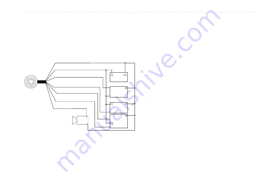
Connecting the Power/Data
The power/data cable connects the GPSMAP 192C to a DC system
and provides interface capabilities for connecting external devices.
The color code in the diagram below indicates the appropriate
harness connections. Replacement fuse is a AGC/3AG - 1.5 Amp
fuse. For wiring the GPSMAP to a GSD 20 Sonar Module, refer to
the “GSD 20 Installation Guide.”
1
2
3
4
5
6
7
PIN 1 (red) Power
PIN 2 (black) Ground (Power and Data)
PIN 3 (blue) NMEA OUT (Com 1 TX)
PIN 4 (brown) NMEA IN (Com 1 RX)
PIN 5 (white) RTCM/NMEA IN (Com 2 RX)
PIN 6 (green) NMEA OUT (Com 2 TX)
PIN 7 (yellow) Alarm Low
NMEA
Device with
Sonar Output
TXD +
Alarm Relay
100ma max
coil current
GSD 20,
Beacon
Receiver or
DSC VHF
Autopilot/
NMEA Device
DC �
Power Source
RXD +
RXD -
RX+
TX+
Complete information regarding NMEA and RTCM formats is
available for purchase at www.nmea.org
Interfacing
The following formats are supported for connection of external
devices:
Garmin proprietary Differential GPS (DGPS), NMEA 0183
versions 2.3, ASCII Text Output, RTCM SC-104 input (vs. 2.0).
The following are the sentences for NMEA 0183, vs. 2.3 output:
Approved sentences
—GPRMC, GPGGA, GPGSA, GPGSV,
GPGLL, GPBOD, GPRTE, and GPWPL.
Proprietary sentences
—PGRME, PGRMZ, and PSLIB. The
GPSMAP 192C accepts NMEA input with support for the DBT,
DPT, MTW, and VHW sentences.
The GPSMAP 192C also includes NMEA input with support for
the WPL sentence and sonar NMEA input with support for the DPT
(Depth), MTW (Water Temp) and VHW (Water Speed & Heading)
sentences. If connecting to COM 2 for sonar NMEA input, the unit
interface must be set to NMEA In/NMEA Out. If connecting to
COM 1, the unit must be set to NMEA In/NMEA Out.
You can download a copy of Garmin’s proprietary communication
protocol on the Help and Support section of our Web site at
www.garmin.com.


