


GMX 200 Installation Manual
Page 5-15
190-00607-04 Revision
D
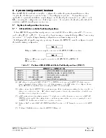
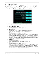
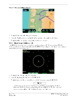
5.4.1.2.1 Calibration of Analog Stabilization Inputs
When in Calibration mode, the GWX 68 is ready to calibrate the stabilization inputs. Each parameter can
be calibrated as described in the sections below.
The GAIN adjustment is used to select the parameter being calibrated. The TILT adjustment is used to
adjust the parameter’s value.
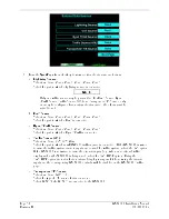
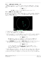
5.4.1.2.2 400HZ Reference Gain
1.
Set the tilt table to 0
°
pitch and roll.
2.
Use the GAIN + and GAIN – keys to set the GAIN to -28. The AZIMUTH ANGLE field should also
display 01.
3.
Use the TILT and TILT
keys to adjust the TILT SETTING. A TILT SETTING between 5 UP
and 10 UP increases the 400 HZ REF field, while a TILT SETTING between 5 DOWN and 10
DOWN decreases the 400 HZ REF field. Use the TILT keys to set the 400 HZ REF field to 0.0
±
1.0
°
. Upon reaching the desired 400 HZ REF setting, quickly set the TILT SETTING to between 5
UP and 5 DOWN to lock in the 400 HZ REF setting.
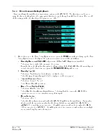
5.4.1.2.3 Pitch Offset
1.
Check that the tilt table is set for 0
°
pitch.
2.
Use the GAIN + and GAIN – keys to set the GAIN to between -17.5 and -19.5. The AZIMUTH
ANGLE field should also display 04. Note that the pitch offset value is displayed in the PITCH
ANGLE field.
3.
Use the TILT and TILT
keys to adjust the TILT SETTING. A TILT SETTING between 5 UP
and 10 UP increases the PITCH ANGLE field, while a TILT SETTING between 5 DOWN and 10
DOWN decreases the PITCH ANGLE field. Use the TILT keys to set the PITCH ANGLE field to
0.0
±
1.0
°
. Upon reaching the desired PITCH ANGLE setting, quickly set the TILT SETTING to
between 5 UP and 5 DOWN to lock in the PITCH ANGLE setting.
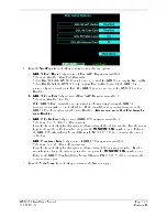
5.4.1.2.4 Roll Offset
1. Check that the tilt table is set for 0
°
roll.
2. Use the GAIN + and GAIN – keys to set the GAIN to between -14 and -16. The AZIMUTH ANGLE
field should also display 05. Note that the roll offset value is displayed in the ROLL ANGLE field.
3. Use the TILT and TILT
keys to adjust the TILT SETTING. A TILT SETTING between 5 UP
and 10 UP increases the ROLL ANGLE field, while a TILT SETTING between 5 DOWN and 10
DOWN decreases the ROLL ANGLE field. Use the TILT keys to set the ROLL ANGLE field to 0.0
±
1.0
°
. Upon reaching the desired ROLL ANGLE setting, quickly set the TILT SETTING to
between 5 UP and 5 DOWN to lock in the ROLL ANGLE setting.
5.4.1.2.5 Pitch Gain
1. Set the tilt table for 10
°
pitch up.
2. Use the GAIN + and GAIN – keys to set the GAIN to between -24.5 and -26.5. The AZIMUTH
ANGLE field should also display 02. Note that the pitch gain value is displayed in the PITCH
ANGLE field.
3. Use the TILT and TILT
keys to adjust the TILT SETTING. A TILT SETTING between 5 UP
and 10 UP increases the PITCH ANGLE field, while a TILT SETTING between 5 DOWN and 10
DOWN decreases the PITCH ANGLE field. Use the TILT keys to set the PITCH ANGLE field to
10.0
±
1.0
°
. Upon reaching the desired PITCH ANGLE setting, quickly set the TILT SETTING to
between 5 UP and 5 DOWN to lock in the PITCH ANGLE setting.
Summary of Contents for GMX 200
Page 1: ...190 00607 04 March 2007 Revision D GMX 200 Installation Manual ...
Page 105: ......
Page 106: ......