


Page 3-6
GMX 200 Installation Manual
Revision D
190-00607-04
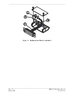
1.
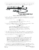
Attach the Shield Block (2) to the backshell (1) by inserting the flathead screws (3) through the holes
on the Shield Block and threading into the tapped holes on the backshell (1). (See Figure 3-1).
Figure 3-2. Shielded Cable Preparation
2.
At the end of the shielded cable (4), strip back a 2” maximum length of the jacket to expose the braid.
Remove this exposed braid. Carefully score the jacket 1/4” to 5/16” from the end and remove the
jacket to leave the braid exposed.
NOTE
Solder sleeves with pre-installed shield drains may be used instead of
separate shield terminators and individual wires.
3.
Connect a 20 or 22 AWG wire (6) to the exposed shield of the prepared cable assembly. (See Figure
3-2). Note: AC 43.13 may be a helpful reference for termination techniques.
NOTE
Solder Sleeves with pre-installed lead:
A preferred solder sleeve is the
Raychem S03 Series with the thermochromic temperature indicator.
These solder sleeves come with a pre-installed lead and effectively take
the place of items 5 and 6. For detailed instructions on product use, refer
to Raychem installation procedure.
4.
Slide a shield terminator (5) onto the prepared cable assembly (4) and connect the wire (6) to the
shield using a heat gun approved for use with solder sleeves. The chosen size of solder sleeve must
accommodate both the number of conductors present in the cable and the wire (6) to be attached.
5.
Repeat steps 2 through 4 as needed for the remaining shielded cables.
NOTE
Each tapped hole on the Shield Block (2) may accommodate only two ring terminals (8).
It is preferred that a maximum of two Wires (6) be terminated per ring terminal. Two
Wires per ring terminal will necessitate the use of a Ring terminal, #8, insulated, 14-16
AWG (MS25036-153). If only a single Wire is left or if only a single Wire is need for
this connector a Ring terminal, #8, insulated, 18-22 AWG (MS25036-149) can
accommodate this single wire. If more wires exist for the connector than two per ring
terminal, it is permissible to terminate three wires per ring terminal.
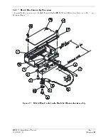
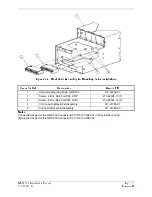
6.
Terminate the ring terminals to the Shield Block (2) by placing items on the Pan Head Screw (9) in
the following order: Split Washer (10), Flat Washer (11), first Ring Terminal, second Ring Terminal
if needed, before finally inserting the screw into the tapped holes on the Shield Block.
Summary of Contents for GMX 200
Page 1: ...190 00607 04 March 2007 Revision D GMX 200 Installation Manual ...
Page 105: ......
Page 106: ......