13–8–609 Page 26
SECTION 5
LUBRICATION
OIL COOLER, OIL FILTER & SEPARATOR
FIGURE 5–1 – FLOW DIAGRAM – AIR–OIL SYSTEM
203EBE797
(Ref. Drawing)
COMPRESSOR OIL SYSTEM (FIGURE 5–1) cools
the compressor, lubricates moving parts and seals in-
ternal clearances in the compression chamber.
The oil inlet line is connected at the bottom of the oil res-
ervoir. Air pressure in the oil reservoir forces oil through
the oil cooler, thermostatic mixing valve, oil filter and
into the compressor main oil gallery.
The oil passes through internal passages for lubrica-
tion, cooling and sealing. The air–oil mixture is then
discharged to the oil reservoir where a large part of
the entrained oil drops out of the air stream; the air
then passes through the final oil separator where most
of the remaining oil is removed. The separated oil is re-
turned to the compressor and the air passes to the final
discharge line.
RECOMMENDED LUBRICANT – Gardner Denver
R
compressors are factory filled with AEON
t
lubricants.
These lubricants are formulated to the highest quality
standards and are factory authorized, tested and ap-
proved for use in rotary screw compressors. AEON
t
lubricants are available through your authorized Gard-
ner Denver compressor distributor.
OIL SPECIFICATIONS – The recommended com-
pressor lubricant is Gardner Denver AEON 4000 Lubri-
cating Coolant which can be used for year–round op-
eration except as noted in the “High Temperature
Operation” paragraph below, or low temperature, see
“Installation for Cold Weather,” page 10. AEON 4000
Lubricating Coolant is a superior petroleum base lubri-
cant formulated and containing additives for use in
Gardner Denver compressors.
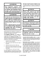
Use of improper lubricants will cause
damage to equipment. Do not mix dif-
ferent types of lubricants or use in-
ferior lubricants.
Summary of Contents for ELECTRA-SCREW EBE DH-15 HP
Page 14: ...13 8 609 Page 6 DECALS 206EAQ077 212EAQ077 218EAQ077 211EAQ077 207EAQ077...
Page 15: ...13 8 609 Page 7 DECALS 216EAQ077 217EAQ077 222EAQ077 221EAQ077 208EAQ077...
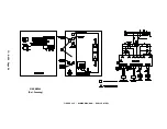
Page 32: ...13 8 609 Page 24 FIGURE 4 10 WIRING DIAGRAM DUAL CONTROL 218EBE546 Ref Drawing...
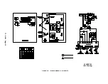
Page 33: ...13 8 609 Page 25 FIGURE 4 11 WIRING DIAGRAM WYE DELTA 220EBE546 Ref Drawing...
Page 51: ......


