13–8–609 Page 9
* 80
o
F (27
_
C) Inlet Air
FIGURE 2–2
Minimum Air Flow* For Compressor
And Cooling – Cubic Feet/Minute
(Cubic Meters/Minute)
Air Cooled
All Models
3000 cfm (170 M
3
/min.)
FOUNDATION – The Electra–Screw
R
compressor re-
quires no special foundation, but should be mounted on
a smooth, solid surface. Whenever possible install the
unit near level. Temporary installation may be made at
a maximum 10
o
angle lengthwise or 10
o
sidewise.
Mounting bolts are not normally required. However,
installation conditions such as piping rigidity, angle of
tilt, or danger of shifting from outside vibration or mov-
ing vehicles may require the use of mounting bolts and
shims to provide uniform support for the base. Belt
alignment and tension should be checked after installa-
tion. (For information on belt alignment and tension see
Section 7, page 35.)
OIL RESERVOIR DRAIN – The oil drain is piped from
the bottom of the reservoir to the side of the frame. This
drain is approximately 2 inches (50 mm) above the floor
level. If this is not sufficient to conveniently drain the oil
some other methods of providing drain are:
1.
Elevate the compressor unit on a suitable struc-
ture to obtain the desired drain height.
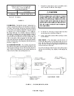
If the compressor unit base is raised
above floor level, the space between
the floor and the base bottom must be
closed with solid material all around
to prevent recirculation of hot air from
the oil cooler end and over tempera-
ture operation.
2.
Construct an oil sump or trough below the floor
level and pump or bail the drained oil.
3.
Pump oil from the reservoir filler opening or drain
to a container.
ENCLOSURE – The compressor, electric motor, oil
cooler and aftercooler are mounted inside the enclo-
sure. Service doors are provided for maintenance ac-
cess. Be sure to allow enough space around the unit
for the doors to be removed.
Any of the enclosure doors may be removed by open-
ing the door and lifting it up slightly to disengage the
hinges.
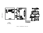
FIGURE 2–3 – COLD WEATHER INSTALLATION
Summary of Contents for ELECTRA-SCREW EBE DH-15 HP
Page 14: ...13 8 609 Page 6 DECALS 206EAQ077 212EAQ077 218EAQ077 211EAQ077 207EAQ077...
Page 15: ...13 8 609 Page 7 DECALS 216EAQ077 217EAQ077 222EAQ077 221EAQ077 208EAQ077...
Page 32: ...13 8 609 Page 24 FIGURE 4 10 WIRING DIAGRAM DUAL CONTROL 218EBE546 Ref Drawing...
Page 33: ...13 8 609 Page 25 FIGURE 4 11 WIRING DIAGRAM WYE DELTA 220EBE546 Ref Drawing...
Page 51: ......


