13–8–609 Page 22
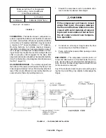
FIGURE 4–6 – SUBTRACTIVE PILOT (CLOSED)
FIGURE 4–7 – SUBTRACTIVE PILOT (OPENED)
The downstream pressure is maintained equal to the
upstream pressure minus a constant which is adjust-
able. In the example shown in FIGURE 4–5, page 21,
the downstream pressure equals the upstream pres-
sure minus 95 psi (6.6 Bars). When the upstream
pressure rises to 100 psig (6.9 Bars), the downstream
pressure rises to 5 psig (.3 Bar). This 1 to 1 psi (Bar)
rise is constant above the set point.
Below the set point, the valve seat is closed and the
downstream pressure is vented. In the example of
FIGURE
4–5, page 21, downstream pressure is
vented below 95 psig (6.6 Bars).
FIGURE 4–6, shows a schematic cross section of the
subtractive pilot with the valve seat closed and down-
stream line vented.
FIGURE 4–7 shows the pilot with valve seat open,
holding a downstream pressure which is adjustable
with the screw. In this position it is normal for the valve
to continually bleed air through the small vent hole in
the bowl.
Moisture, oil and dirt in the control system lines and
components can cause the set point of the subtractive
pilot to shift or be erratic. The subtractive pilot can be
disassembled and the diaphragm and ports cleaned
when necessary.
Operating Air Pressure Adjustment – The Auto–
Sentry S controller load and unload pressure setpoints
should already be programmed. See page 19, and
FIGURE 4–8, page 23.
Operation at excessive discharge air
pressure can cause personal injury or
damage to equipment. Do not set un-
load pressure above the maximum
stamped on the unit nameplate.
To adjust the subtractive pilot:
1.
With the unit off, loosen the locknut and back out
the adjusting screw several turns so the subtrac-
tive pilot will fully unload the compressor before
the unload pressure setpoint of the microproces-
sor controller is reached.
2.
Close the air service valve and start the unit in
the “CONSTANT RUN” mode. Allow unit to
reach the pressure at which the subtractive pilot
fully unloads the compressor.
3.
Turn–in the adjusting screw until the unload
pressure setpoint is reached and the micropro-
cessor controller allows the unit to blow down.
4.
Turn–in the adjusting screw an additional one–
eighth (1/8) turn and tighten the locknut. As a re-
sult, the subtractive pilot will not fully unload the
compressor before the microprocessor control-
ler’s unload pressure setpoint is reached.
5.
Using the air service valve, cycle the unit be-
tween load and unload several times to be cer-
tain that the unit will reach the microprocessor
controller’s unload pressure setpoint and blow
down.
Summary of Contents for ELECTRA-SCREW EBE DH-15 HP
Page 14: ...13 8 609 Page 6 DECALS 206EAQ077 212EAQ077 218EAQ077 211EAQ077 207EAQ077...
Page 15: ...13 8 609 Page 7 DECALS 216EAQ077 217EAQ077 222EAQ077 221EAQ077 208EAQ077...
Page 32: ...13 8 609 Page 24 FIGURE 4 10 WIRING DIAGRAM DUAL CONTROL 218EBE546 Ref Drawing...
Page 33: ...13 8 609 Page 25 FIGURE 4 11 WIRING DIAGRAM WYE DELTA 220EBE546 Ref Drawing...
Page 51: ......


