background image

5

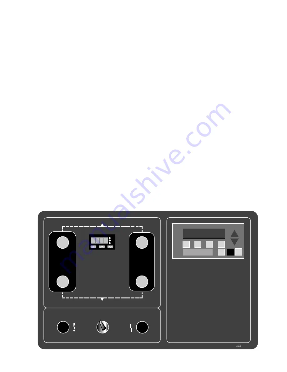
Figure 4.1 - Control Panel

4.0

Operation

4.1  Controls

A programmable logic controller (PLC) controls valve,
blower, and heater operation, monitors all critical
operating conditions, and indicates operating status and
fault conditions on an LCD display.  The PLC receives
digital input data from pressure switches, temperature
switches and the operator interface.  The operator
interface displays information about the dryer operat-
ing status and is used to change the dryer operating
mode.

4.2  Operating Modes - Description

A.  Automatic and Manual Advance

The drying and regeneration cycles are divided into
discrete steps.  The operator selects either auto-
matic or manual advance through the operator
interface.  Selecting automatic advance enables a
timer in the PLC which advances the program step-
by-step according to the programmed schedule.
This is the normal operating mode to be used.
Selecting manual advance disables the PLC’s internal
timer and the operator can advance the program
one step at a time.  This mode is used for diagnos-
tic purposes.

B.  Auto-stop Mode

In this mode of operation the dryer program will
automatically stop when it reaches the beginning of
the next drying cycle.  Auto-stop should be used
when the dryer is shut-down.  This allows the
current regeneration cycle to be completed
without interruption and ensures that dry air will be
available when the dryer is restarted.

Auto-stop can only be enabled if automatic advance
is selected.  Auto-stop can be used in either fixed
or demand cycle operation.  When used with
demand cycle operation the dryer switches to a

fixed cycle; when the dryer is returned to normal
operation (auto-stop disabled) the dryer will return
to demand cycle operation.

Auto-stop is enabled or disabled through the opera-
tor interface.  The dryer can be returned to normal
operation at any time by disabling auto-stop.

C. Fixed and Demand Cycle Operation

In fixed cycle operation, each tower is on-line
(drying) for a fixed time period regardless of the
operating conditions.  In demand cycle operation, a
tower remains on-line until the desiccant bed has
been fully utilized.  For lower than designed mois-
ture loads, this results in longer drying cycles,
longer time between regenerations and, therefore,
lower energy consumption.  Demand cycle opera-
tion is an optional feature.  The operator interface is
used to select the fixed or demand cycle.

D.   Optional Dew Point Monitor

This option monitors and displays outlet pressure
dew points (-130

°

F to +50

°

F, -90

°

C to +10

°

C) and

provides an alarm signal if the dew point exceeds
user-specified set point.  Field calibration may be
performed without taking it off-line or removing it
from the system.  Recommended calibration
interval is 12 months.  Contact the service depart-
ment for details.

Operation - The dew point is measured at the dryer
operating pressure and is displayed in Menu #1 on
the operator interface.  If the dew point is outside
of the measurement range, display will indicate an
over-range (high dew point) or under-range (low
dew point) condition.  A defective sensor assembly
or an electronics malfunction could also cause the
transmitter to indicate under-range.

OUTLET/Salida/Sortie

HEATER TEMPERATURE

Temperatura del Calentador

Température Du Réchauffeur

DRYING

Secando
Séchage

REGENERATING

Regenerando
Régénération

REGENERATING

Regenerando
Régénération

DRYING

Secando
Séchage

INLET/Entrada/Entrée

I

O

1
2

RDY

F1

F2

F3

F4

OPERATOR INTERFACE

Summary of Contents for DEB Series

Page 1: ...vicing B Electrical This equipment requires electricity to operate Install equipment in compliance with national and local electrical codes Equipment supplied as standard is not intended for installat...

Page 2: ...alternated on and off line so that dry desiccant is always in contact with the wet com pressed air resulting in a continuous supply of dry air downstream The switching from one tower to the other is...

Page 3: ...perature and capable of removing all desiccant fines 1 micron and larger should be provided The use of bypass valves and piping allows servicing of the filters and or dryer without interrupting the ai...

Page 4: ...Valve Purge Exhaust Left Purge Valve Left Purge Pilot Valve Left Inlet Valve Left Inlet Pilot Valve Purge Exhaust Muffler Right Depressurization Valve Temperature Gauge Back Front Air Inlet Left Depr...

Page 5: ...s returned to normal operation auto stop disabled the dryer will return to demand cycle operation Auto stop is enabled or disabled through the opera tor interface The dryer can be returned to normal o...

Page 6: ...the right tower and exits through the right purge valve V4 The blower intake air is filtered F1 to keep dust and dirt from entering the dryer The blower B1 and heater H1 are de energized when the temp...

Page 7: ...The pressure in the right tower begins to rise and check valve V10 is seated Next the repressurization valve V15 is closed and the depressurization valve V6 is opened depressurizing the tower Finally...

Page 8: ...all times 4 The F4 key performs three different functions as described in Menu s 3 4 and 5 The F4 key is only active when one of these menus is displayed 5 Use the UP ARROW and DOWN ARROW triangular...

Page 9: ...4 to identify the active alarm s Then refer to the Troubleshooting Guide Section 5 0 for help in correcting the alarm condition After correcting an alarm condition use the F1 key on the operator inte...

Page 10: ...ized Q1 0 9SOL Repressurization pilot valve When the solenoid is energized pilot air opens the repressurization valve when de energized pilot air closes the repressurization valve Q1 1 M Blower motor...

Page 11: ...3 PLC Inputs Left Tower Drying and Outputs Step Number I O No Device L00 L01 L02 L03 L04 L05 L06 L07 L08 L09 L10 L11 L12 L13 L14 L15 I0 0 LPS I0 1 RPS I0 2 BPS I0 3 HHC I0 4 LTS I0 5 RTS I0 6 DPM I0 7...

Page 12: ...r I O No Device L00 L01 L02 L03 L04 L05 L06 L07 L08 L09 L10 L11 L12 L13 L14 L15 I0 0 LPS I0 1 RPS I0 2 BPS I0 3 HHC I0 4 LTS I0 5 RTS I0 6 DPM I0 7 Jumper 1 I1 0 Jumper 2 I1 1 I1 5 Not Used Q0 0 1 SOL...

Page 13: ...valve to on line tower L01 R01 0 5 0 5 Close inlet valve to off line tower L02 R02 4 0 4 0 Depressurize off line tower L03 R03 0 5 0 5 Examine off line tower pressure switch L04 R04 0 5 0 5 Open purg...

Page 14: ...exhaust piping indicating valve is not completely closed Check for loss of pilot air see Section 5 1 4 Check for left purge pilot valve V13 failure check valve operation Repair or replace as necessar...

Page 15: ...eration cycle 1 False alarm Heater hi limit thermocouple check thermocouple circuit for continuity Repair or replace as necessary Heater hi limit controller TC2 or TC4 malfunction check controller ope...

Page 16: ...upply Check compressor supplying dryer 2 Excessive air demand Check equipment downstream of dryer 3 Faulty right tower pressure Check pressure switch operation using right tower pressure gauge switch...

Page 17: ...clean or replace 2 Improper setting on blower pressure Check pressure switch operation Readjust switch setting or replace switch PS3 switch if defective 3 Loss of pressure to blower pressure Check lin...

Page 18: ...ee Section 5 9 3 2 Right purge valve V4 failed to close See Section 5 9 5 3 Right depressurization valve V6 See Section 5 9 6 failed to close 4 Repressurization valve V15 failed Loss of pilot air see...

Page 19: ...motor instruction tag 6 3 Blower Pressure Switch The blower pressure switch located in the main electrical enclosure is adjustable Verify that the switch is open when the blower is off and closed whe...

Page 20: ...ages liability of the manufacturer is the original purchase price of the product or part THE FOREGOING WARRANTY IS EXCLUSIVE AND IN LIEU OF ALL OTHER WARRANTIES WHETHER WRITTEN ORAL OR STATU TORY AND...

Reviews: