background image

0 cm / 0"

3.4.3.4 To make a secondary area
Make a secondary area (B) if the work area has 2 areas

that are not connected with a passage. The work area

with the charging station is the main area (A).

B

A

Note: 

The product must be manually moved between

the main area and the secondary area.

Put the boundary wire around the secondary area

(B) to make an island. Refer to 

To make an island

on page 14

.

Note: 

The boundary wire must be put as 1 loop

around all of the work area (A + B).

Note: 

When the product cuts grass in the

secondary area, the 

Secondary area

 mode must

be selected. Refer to 

Secondary area on page

23

.

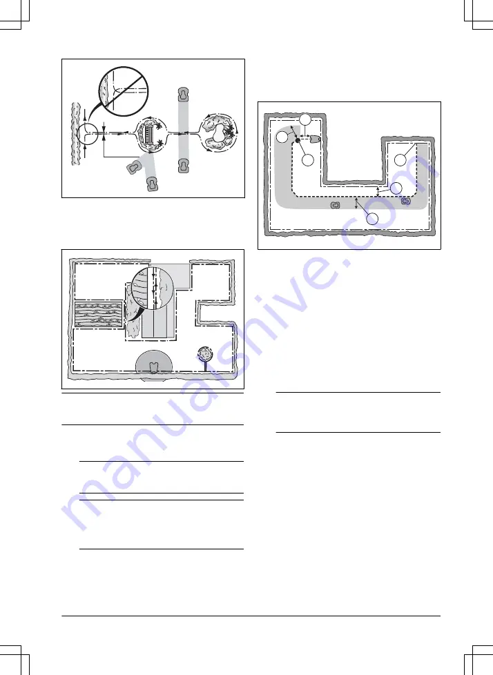
3.4.4 To examine where to put the guide

wire

Put the guide wire from the charging station through the

work area and connect it to the boundary wire.

F

D

C

E

A

B

Put the guide wire in a line at a minimum of 1 m /

3.3 ft. in front of the charging station (A).

Put the guide wire minimum 30 cm / 1 ft. from the

boundary wire (B).

Starting point (C). Refer to 

Starting point on page

20

.

Minimum distance 60 cm / 2 ft. perpendicular to the

guide wire (D).

Where the guide wire is connected to the boundary

wire (E).

Guide corridor (F). The product always runs to the

left of the guide wire as seen facing the charging

station. Make sure that the guide wire has as much

free area as possible to the left of the guide wire.

The guide corridor can be maximum 1.2 m / 4 ft.

Note: 

The product always runs in the guide

corridor but changes the distance to the guide

wire.

3.4.5 Work area examples

If the charging station is put in a small area (A),

make sure that the distance to the boundary wire is

at a minimum 2 m / 6.6 ft. in front of the charging

station.

If the work area has a passage (B) with no guide

wire installed, the minimum distance between the

boundary wires is 2 m / 6.5 ft. With a guide

wire installed through the passage, the minimum

distance between the boundary wires is 60 cm /

24 in. Use the 

CorridorCut

 function to cut this

passage, Refer to 

Lawn Coverage and CorridorCut

on page 19

.

If the work area has areas which are connected by

a narrow passage (B), you can set the product to

first follow and then leave the guide wire after a

1585 - 007 - 26.10.2022

Installation - 15

Summary of Contents for SILENO minimo

Page 1: ...gardena com Operator s manual SILENO minimo...

Page 2: ...ire 18 3 9 After the installation of the product 18 3 10 To do the product settings 18 4 Operation 4 1 To use the ON OFF button 22 4 2 To start the product 22 4 3 Operating modes 22 4 4 To stop the pr...

Page 3: ...F before you clear a blockage do maintenance or examine the product and if the product starts to vibrate abnormally Examine the product for damage before you start the product again Do not use the pro...

Page 4: ...low the product when it is set to ON Use the park mode or set the product to OFF when persons especially children or animals are in the work area Refer to Park on page 23 GARDENA recommends to set the...

Page 5: ...the STOP button and pull the product out of the charging station before you lift it To safely move the product from or in the work area 1 Push the STOP button to stop the product 2 Push the ON OFF bu...

Page 6: ...the product turns around When the product hits an obstacle or approaches the boundary wire the product selects a new direction You can select the operation settings in the GARDENA Bluetooth App or wi...

Page 7: ...15 Torx for cutting height adjustment1 16 Rating plate2 17 Stakes 18 Connector for the loop wire 19 Couplers for loop wire 20 Screws to attach the charging station 21 Power supply 3 22 Loop wire for...

Page 8: ...pose to water fire or high temperature Read the user instructions Do not discard the battery into fire and do not expose the battery to a heat source Do not immerse the battery into water 2 5 General...

Page 9: ...cator on the keypad The LED status indicator on the keypad shows the status of the product There are 2 light modes on the LED status indicator flashing light A and solid light B A B Standby Idle 1585...

Page 10: ...Waiting for PIN code Wrong PIN code Cutting according to set Schedule Cutting either in operating mode Override schedule or Secondary area Parked Error 10 Introduction 1585 007 26 10 2022...

Page 11: ...e a blueprint of the work area and include all obstacles This makes it easier to examine where to put the charging station the boundary wire and the guide wire Make a mark on the blueprint where to pu...

Page 12: ...dual current device RCD with a tripping current of maximum 30 mA when you connect the power supply to the power outlet Low voltage cables of different lengths are available as accessories 3 4 3 To exa...

Page 13: ...the lawn put the boundary wire below the paving stone Note If the paving stone is minimum 30 cm 12 in wide use the factory setting for the Drive Past Wire function to cut all the grass adjacent to the...

Page 14: ...de wire A A 30 cm 12 60 cm 24 3 4 3 3 To make an island CAUTION Do not put a section of boundary wire across the other The sections of boundary wire must be parallel CAUTION Do not put the guide wire...

Page 15: ...Minimum distance 60 cm 2 ft perpendicular to the guide wire D Where the guide wire is connected to the boundary wire E Guide corridor F The product always runs to the left of the guide wire as seen fa...

Page 16: ...he charging station on page 11 2 Put the charging station in the selected area Note Do not attach the charging station to the ground with the screws until the guide wire is installed Refer to To insta...

Page 17: ...1 2 cm 0 4 0 8 in above each connector 4 Push the guide wire through the slot in the charging station plate 5 Push the connector onto the metal pin on the charging station with the mark G 6 Disconnec...

Page 18: ...t you can see the ends of the boundary wire or the guide wire through the transparent area of the coupler 6 Push down the cover on the coupler with adjustable pliers to attach the wires in the coupler...

Page 19: ...maximum cutting time in a day the message Today s mowing complete is shown in the display of the app The recommended operating times for some work area examples are shown in the table below If the res...

Page 20: ...le for SensorControl Do not restrict the schedule more than necessary Also check that the blade disc is clean and that the blades are in good condition The first operation of the day is set by the sch...

Page 21: ...se the product for the first time you must enter the factory PIN code You can change the PIN code in the GARDENA Bluetooth App Note The ON OFF button the Park button the Start button and the Start Sch...

Page 22: ...product has cut the grass for some time the perceived sound level is much lower 4 3 Operating modes The following operating modes are available Main area Secondary area Park Park Schedule Override sc...

Page 23: ...ark the product This can be set in the dashboard in the app or with the keypad on the product 1 Push the STOP button 2 Push the Park button for 3 seconds 3 Push the OK button Note To change the operat...

Page 24: ...tery WARNING Only charge the product using a charging station which is intended for it Incorrect use may result in electric shock overheating or leakage of corrosive liquid from the battery In the eve...

Page 25: ...ver clockwise by hand and remove it 4 Remove the torx that is attached to the body of the product 5 Turn the product upside down 6 Remove the 2 screws on the blade disc 7 Lift up the blade disc 8 Inst...

Page 26: ...eak to your GARDENA service for more information 5 2 1 To clean the chassis and blade disc Examine the blade disc and blades weekly 1 Push the STOP button 2 Push the ON OFF button for 3 seconds to set...

Page 27: ...blade disc up on a soft and clean surface 4 Remove the 3 screws 5 Remove each blade and screw 6 Attach new blades and screws 7 Make sure that the blades can pivot freely 5 4 Firmware update If servic...

Page 28: ...rs of operation a day means that the battery must be replaced more regularly 5 6 1 To replace or to remove the battery WARNING Use protective gloves CAUTION Do not touch the circuit boards 1 Push the...

Page 29: ...n out of the channel 17 Attach the sealing strip in the retainer 18 Install the upper chassis and attach the 10 screws with a Torx 20 Screw torque 1 8 Nm 5 7 Winter service Take your product to your G...

Page 30: ...roduct is behind a number of obsta cles in a small area Remove the obstacles or put the boundary wire around the obstacle to make an is land Refer to To make an island on page 14 Outside working area...

Page 31: ...product The work area includes a steep slope Steep slopes must be isolated Refer to To examine where to put the boundary wire on page 12 The guide wire is not put diagonally in the slope Make sure tha...

Page 32: ...fety function faulty Charging system problem There is corrosion or dirt on the charging plates and contact plates Restart the product Clean the charging plates on the product and the contact plates on...

Page 33: ...e The product has tried to start but it is not in the charging station and ECO mode is ena bled Put the product in the charging station and start the product A section of the boundary wire is across t...

Page 34: ...arging station Refer to To install the guide wire on page 17 Damage in the guide wire Replace the damaged section with new guide wire The guide wire is not connected to the boundary loop Connect the g...

Page 35: ...stalled in the charging station Refer to To install the boundary wire on page 17 Damage in the boundary wire Find out where the damage is Replace the damaged section with new boundary wire Yellow flas...

Page 36: ...necessary Refer to Replacement of the blades on page 27 The cutting system is not in balance because of too many blades in the same position Do a check that only one blade is attached to each screw D...

Page 37: ...ct goes back to the charging station To prevent to become blocked in a small area the product follows the guide wire to the charging station Usual operation for the product 6 6 Find breaks in the loop...

Page 38: ...wire is connected to the boundary wire thick black line in the illustration Guide GUIDE L To rectify the fault you will need boundary wire connector s and coupler s a If the suspected boundary wire i...

Page 39: ...ch is the difference between a solid green light and a flashing blue light Then follow instruction in step 5 below 4 If indicator lamp still flashes blue in step 3 above Put L and GUIDE back in their...

Page 40: ...Keep the product in a dry frost free space Keep the product with all wheels on level ground during storage If you keep the charging station indoors disconnect and remove the power supply and all the c...

Page 41: ...m use 4 kWh month in a 500 m2 work area Charge current A DC 1 1 3 Type of Power Supply Unit5 ADP 28AW XX ADP 28AR XX ADP 40BR XX ADP 40EW XX FW7313 28 D XX Y 1 0 FW7313 28 D XX Y 1 0 PI FW7313 28 D XX...

Page 42: ...itted power dBm 8 Husqvarna AB does not guarantee full compatibility between the product and other types of wireless systems such as remote controls radio transmitters hearing loops underground electr...

Page 43: ...mful interference and this device must accept any interference received including interference that may cause undesired operation Note This equipment has been tested and found to comply with the limit...

Page 44: ...ORIGINAL INSTRUCTIONS We reserve the right to make changes without prior notice Copyright 2022 GARDENA Manufacturing GmbH All rights reserved 1143084 95 2022 11 15...

Reviews: