RTCC LED lighting controllers - User Manual
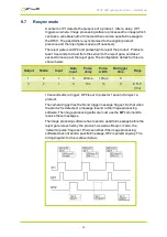
Output
Mode
Input
Gate
input
Pulse
delay
Pulse
width
Retrigger
time
Flags
1
2
1
0
100ms
100μs
0
(0)
2
2
1
0
200ms
100μs
0
(0)
Both outputs are set to pulse mode. Two different delays give the timing
difference between the two cameras.
9.3
Gated pulses
A camera needs to be triggered at 25Hz continuously, except when IP1 is
high to indicate that the machine has stopped. The camera is triggered on
OP1. The configuration details for this are shown below:
Output
Mode
Input
Gate
input
Pulse
delay
Pulse
width
Retrigger
time
Flags
1
2
0
1
0ms
100μs
0
G (4)
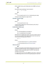
Set free-running trigger to 25Hz
OP1 triggers continuously at 25Hz only when IP1 is low.
Note:
Flags are set
to 4 to invert the sense of IP1. If Flags are set to 0, then OP1 only triggers
when IP1 is high. The timing diagram is shown below:
—
36
—


