


28
14. TENSION ADJUSTMENT
Your preassembled rail comes with the tension adjusted to factory
specifications. There should be no need for further adjustment. However,
if exposed or subjected to unusually harsh operating conditions, the ten-
sion may need to be readjusted during the life of the opener.
CHECK PROPER TENSION (Fig. 44):
• Release trolley from belt or chain, then examine the setting of the tension
adjustment at the header end of the rail.
• Proper tension is set when the tension nut is tightened just enough so that
the washer will be spaced approximately 1mm or 3/64” from the
stationary rail end-stop arch.
• If the gap between the washer and the rail end-stop arch is too big or too
small, the tension needs to be adjusted.
ADJUST THE TENSION:
• To increase the tension and tighten the belt or chain, turn the tension nut
clockwise with 7/16” wrench until the washer is spaced properly from the
rail end-stop arch (see Fig. 44).
• Once the washer is spaced correctly, any additional tightening will
overtighten the belt or chain and may cause damage to the system.
• To loosen the tension, turn nut counterclockwise.
• Reattach trolley.
Proper Tension Adjustment
Rail End Stop
(Header End)
Tension Nut
Washer
Roller Holder Assembly
Proper Space (1mm or approximately 3/64”)
Fig. 44
960 mm (37-3/4”)
Tab Location
Fig. 44A
15. RAIL LENGTH ADJUSTMENT
FOR PROFESSIONAL INSTALLERS ONLY
If your particular installation calls for a shorter rail than the standard length
provided, it is possible to shorten the rail.
NOTE:
Shortening rail too much may result in door travel length reduction
and door not opening fully. This depends on door size and configuration.
Carefully plan all such modifications before proceeding. THIS PROCEDURE
SHOULD BE PERFORMED ONLY BY A PROFESSIONAL INSTALLER
FULLY FAMILIAR WITH THIS TYPE OF OPENER SYSTEM.
TO SHORTEN BELT RAIL LENGTH:
• Loosen belt tension as much as possible.
• Remove screws from sprocket holder and rail end-stop.
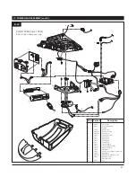
• Slide belt and all rail parts out of rail from header end. See rail exploded
view, Fig. 46 on p. 29, for disassembly details.
• Measure and cut off excess rail from header end.
• Using rail end-stop as a guide, mark and drill two 3/16” holes on rail sides
for rail end-stop screws.
• Disassemble connector to expose free ends of belt.
• Using the same measurement as the excess rail length, cut the same
mount off BOTH free ends of the belt.
• Reassemble belt connector, and slide all rail parts into rail from header end
ccording to original assembly (see Fig. 44 and Fig. 44A).
• Tension belt properly (see Fig. 44).
• Check rail for proper assembly and operation by manually moving trolley
from end to end and back to position per Fig. 44A, with trolley connected
to belt.
Chain Link
Chain Strap
1”
Fig. 45
TO SHORTEN CHAIN RIAL LENGTH:
• Loosen chain tension as much as possible.
• Remove screws from sprocket holder and rail end-stop.
• Slide chain and all rail parts out of rail from header end. See rail
exploded view, Fig. 47 on p. 29, for disassembly details.
• Measure and cut off excess rail from header end by 1” increment only.
• Using rail end-stop as a guide, mark and drill two 3/16” holes on
rail sides for rail end-stop screws.
• Disassemble connector to expose free ends of chain.
• Using the same measurement as the excess rail length, remove the
same amount off chain links and chain straps from BOTH free ends
of the chain (see Fig. 45).
• Reassemble two piece connector and slide chain and all rail parts
into rail from header end according to original assembly (see Fig.
44 and Fig. 44A).
• Tension chain properly (see Fig. 44).
• Check rail for proper assembly and operation by manually moving
trolley from end to end and back to position per Fig. 44A, with
trolley connected to chain.
Summary of Contents for CarGO 500
Page 1: ......


