


EG-8
Connecting the cables
Connect the power cable and the LAN cable.
Attention
Check if the power supply is “OFF.”
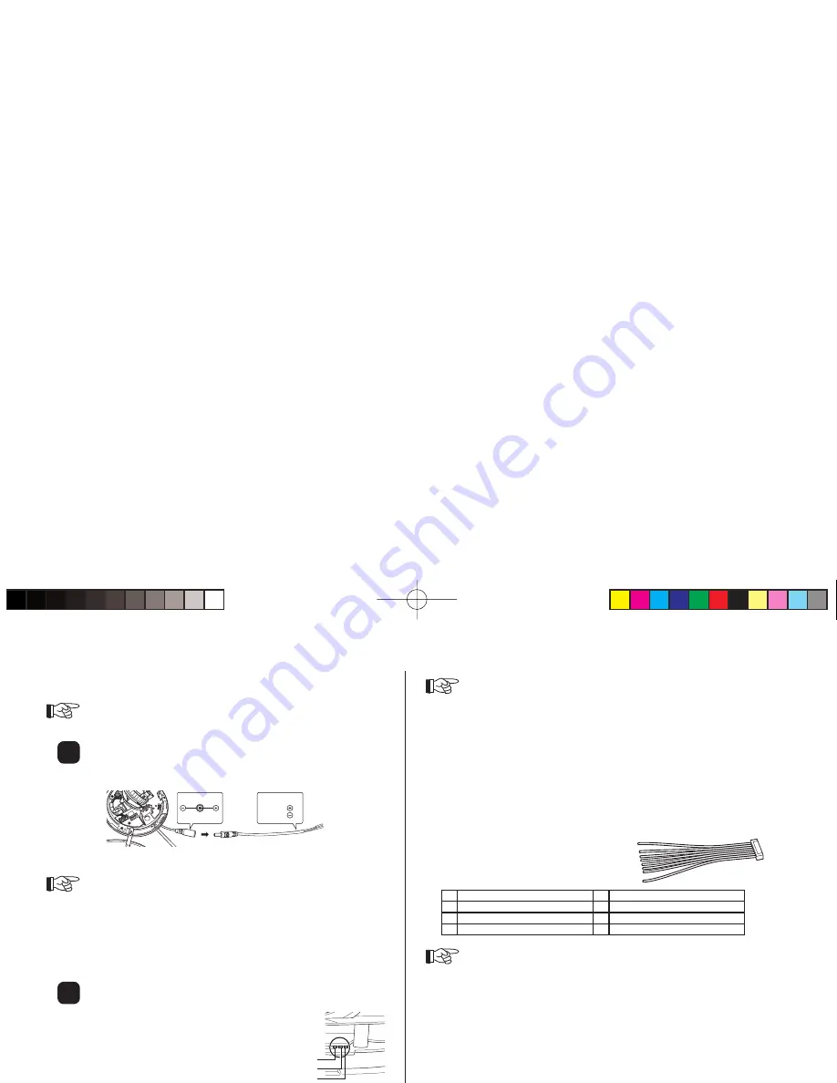
Connecting the power supply cable.
1
Connect the power cable (plug) included to the power source. In
the case of 12 V DC, connect the red cable to 12 V DC and the
black cable to the GND.
DC12V
RED
BLACK
2
Connect the power cable (plug) connected in Step 1 above to the
power cable (jack) of the camera body.
Attention
When connecting the power source directly to the power input terminal of
the camera body without using the power cable (plug) included, be sure to
use a heat-resistant cable (resistant to the temperature higher than 75°C).
When connecting the 12 V DC power directly to the power input terminal
of the camera body without using the power cable (plug) included, be sure
to align “+12 V DC” with “GND” that are displayed near the terminal of the
board.
Connecting the LAN cable.
Connect the LAN cable to the LAN cable (jack) of the camera body.
When the LAN cable is connected, the LAN cable
connection confi rmation LED (orange) lights up. The
LED (yellow) or (green) is fl ashing according to Receive
and Transmit.
Attention
When the power is supplied at the same time from the PoE power source
and the power cable, the power cable line is used.
When the PoE power source is used, the connection of the power cable is
not required.
Use CLASS 2 power supply when you use 24 V AC.
Be sure to check that the cables are connected correctly before turning the
power on.
Turning on the power when the cables are connected with incorrect polarity
may damage the camera.
Be sure to use a LAN cable of category 5 or above.
Connection of I/O cables
When using an alarm and/or a speaker,
connect the I/O cables to the I/O cable
terminals provided on the camera body.
Wiring of I/O cable
1 (Brown) Input
5 (Green) Speaker (Output)
2 (Red) GND
6 (Blue) GND
3 (Orange) Output
7 (Purple) Microphone (Input)
4 (Yellow) Output
8 (Grey) GND
Attention
“1” is an alarm input terminal with no-voltage make-contact input (3.3 V DC
pull-up resistor built-in, short circuit current is 0.4 mA).
“3” and “4” are alarm output terminals with contact output (30 V DC, 1 A
- 125 V AC 0.3 A).
2
1
Receive (Yellow)
Connection confi rmation (Orange)
Transmit (Green)
(US)ZN-D9024NTSC.indd 8
(US)ZN-D9024NTSC.indd 8
2009/02/27 17:15:04
2009/02/27 17:15:04
Summary of Contents for zn-d9024nha
Page 1: ......


