EG-5
INSTALLATION AND ADJUSTMENT
Attaching to the surface of the ceiling or wall
This section explains how to install the unit where cables are running
through the interior of the ceiling or wall. When running cables on the
exterior surface of the ceiling or wall, please drill holes in the ceiling
or wall as directed in step 1, then refer to “Running cables on the
exterior surface of the ceiling or wall” (page EG-6).
Drilling holes in the ceiling or wall
Use the template included to mark out the position on the ceiling or
wall where you want to install the unit.
When running cables through the interior of the ceiling or wall
Use the template, and drill three holes. Two for screws (Screw A) used to
attach the camera body and one for the cables (Cables).
When running cables on the exterior surface of the ceiling or wall
Use the template, and drill two holes for screws (Screw A) used to attach
the camera body.
Connecting the cables
For details of the cable connection, refer to “Connecting the cables”
(page EG-8).
Attaching the camera body
1
Remove the body cover.
2
Attach the camera body to the
ceiling or wall.
Please use fi xing screws suitable
for the material of the ceiling or
wall when attaching the camera
body. We recommend using
screws with 4 mm diameter.
When you fi nish attaching the camera, refer to page EG-8.
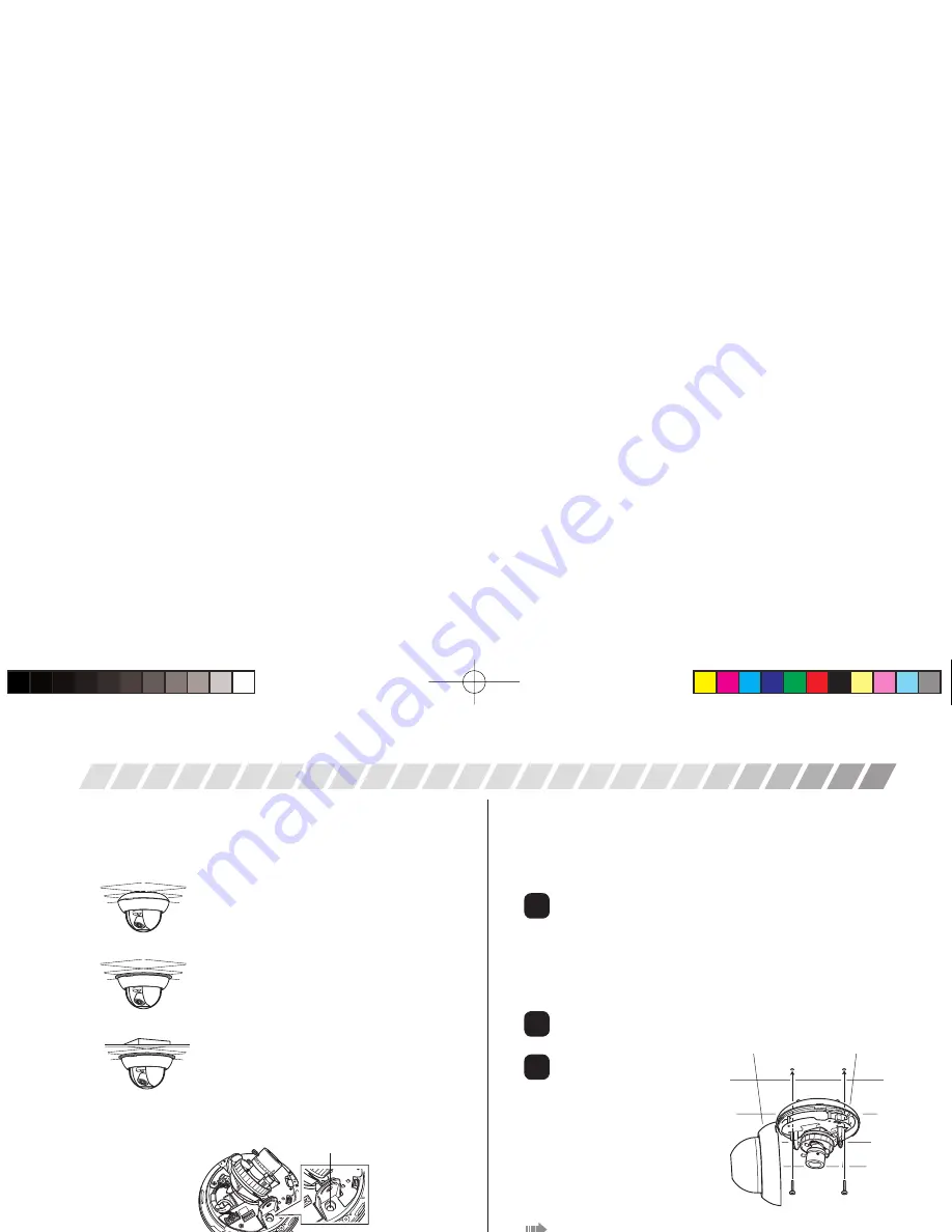
Attaching the unit
You can use the following three methods to attach the unit. Please
use the method that best fi ts the conditions of the area in which you
want to install the unit.
Attaching to the surface of the ceiling or wall
Use this method to attach the unit to the surface of
the ceiling or wall (right of this page).
Embedding in the ceiling or wall
Use this method to attach the unit by embedding it
in the ceiling or wall (page EG-6).
Be sure to use the adapter ring to attach the
camera.
Attaching to a 4S junction box
Use this method to attach the unit when a 4S
junction box is available (page EG-7).
Be sure to use the adapter ring to attach the
camera.
Before attaching the unit
When attaching (or removing) the unit, turn the camera body to bring
together the two screw holes as shown in the drawing below.
2
1
3
screw holes
(US)ZN-D9024NTSC.indd 5
(US)ZN-D9024NTSC.indd 5
2009/02/27 17:15:01
2009/02/27 17:15:01
Summary of Contents for zn-d9024nha
Page 1: ......


