Ganz ZC-Y20PH Instruction Manual Download Page 8

8

8. ADJUSTMENT

1. Supply power to the camera. The power indicator 

will light.

2. Flickering of lighting may interfere with the view when the camera is used in the room in the area with

power frequency of 60 Hz. To view the flickering-free picture, shift the flickering-reduction switch of the
mode switch 

to "1/120" position. 

Note
Placing the flickering-reduction switch in the "1/120" position makes the sensitivity lower than in the "(1/50)"
position. Use the "(1/50)" position when the flickering does not interfere with the view or when the camera
is used in dark locations.

3. Connect the video output terminal 

to the monitor so that the picture may be displayed on the monitor.   

4. Adjust the camera angle viewing the monitor screen.

5. Adjust the lens for the best possible picture reproduction.

When using the DC input type lens, adjust the sensitivity with the iris control 

.

When using the VIDEO input type lens, adjust the sensitivity with the ALC or LEVEL control of the lens.

Notes

Because the iris control is set to the optimum position by the factory, avoid handling it. Rotating the
control more than required could downgrade the image quality or result in camera malfunction. When
readjusting the camera, first set the AGC switch of the mode switch to "OFF" position, then adjust the
iris control for the best possible picture reproduction. After adjustment completion, cover the lens front
with the hand and remove it from the lens a few seconds later. If you find the lens iris is functioning
correctly, shift the AGC switch back to "(AGC)" position. 

The object that was brought into focus in bright locations could be out of focus in dark conditions. In
such cases, use a commercial ND filter for focus adjustment. 

When the distance to an object is shorter than the lens' shortest focusing distance or when a zoom lens
is used, if the object is out of focus, adjust the camera as instructed below (back focal length
adjustment):

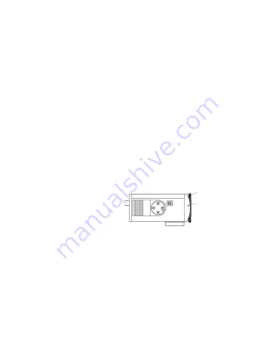
5-1. Attach a lens to the camera.
5-2. Loosen the back focal length

adjustment ring fixing screw 

.

5-3. Rotating the back focal length

adjustment ring 

, adjust it to the

optimum position. 

5-4. Retighten the back focal length

adjustment ring fixing screw.

6. Set the synchronizing method using the synchronization selector switch of the mode switch 

.

One of the following methods can be selected: internal locking (switch position: "INT"), line locking ("LL"
position), and vertical signal external locking ("INT" position). In this setting, when the camera is connected
to other equipment capable of using vertical signal external locking, the method is automatically switched
from internal locking to vertical signal external locking. When using the line locking method, set the
synchronization switch to "LL" position. 
Note
You cannot use the line locking method in the area where the power frequency is 60 Hz.   

7. Using the vertical phase control 

, synchronize the camera. (This adjustment is required only for line

locking mode.) When using multiple line-locked cameras ("LL" position) and switching camera outputs by
means of a sequential switcher, the pictures may be distorted depending on the distance to the power
source or camera installation conditions. In such cases, turn the vertical phase control to avoid the picture
distortion.   

② 

Back focal length 


adjustment ring

① 

Back focal length 


adjustment ring fixing 


screw

Summary of Contents for ZC-Y20PH

Page 1: ...COLOUR CS MOUNT CAMERA 230VAC TYPE ZC Y20PH3 24VAC 12VDC TYPE ZC Y20PH4 INSTRUCTION MANUAL ZC Y20PH...

Page 2: ...onal Selection and Camera Setting 7 7 2 Auto Iris Lens Installation 7 8 ADJUSTMENT 8 9 CAMERA FUNCTION SETTING 9 Iris Level Setting 10 Shutter Speed Flickering Reduction Operation Setting 11 Backlight...

Page 3: ...ally for safety use Deterioration of the installed part may cause dropping of the unit resulting in personal injury and or property damage Contact your CBC dealer as to the periodical inspection When...

Page 4: ...dry soft cloth Never use such volatile liquids as benzine and thinner because the camera may be discolored or deformed To clean the camera lens use an ear syringe or photographic lens tissue to blow...

Page 5: ...0PH4 Note Controls and are exposed when you move the cover toward the rear panel Back focal length adjustment ring fixing screw Back focal length adjustment ring Lens connector Menu key Lens selector...

Page 6: ...aded hole in the mount 3 Set the camera s direction then fix the camera by rotating the lock lever Note The mount can be installed on either the top panel or bottom panel of the camera and is installe...

Page 7: ...et the flickering reduction switch of the mode switch to 1 50 position Factory preset for 1 50 position Notes When the flickering reduction switch is set to 1 120 position the automatic sensitivity ad...

Page 8: ...that was brought into focus in bright locations could be out of focus in dark conditions In such cases use a commercial ND filter for focus adjustment When the distance to an object is shorter than t...

Page 9: ...ically maintained constant automatically changed or set for OFF Also a sensitivity level can be changed in increments of OFF 2 times 4 times 6 times 8 times 10 times 16 times 24 times or 32 times 5 Wh...

Page 10: ...screen is displayed with the iris type automatically set for either auto iris when the iris selector switch is placed in the AUTO position or manual iris when the iris selector switch is placed in th...

Page 11: ...e speed is set for AES 11 Shutter Speed Flickering Reduction Operation Setting Shutter speed setting screen You can set the shutter speed to NORMAL 1 50 1 120 flickering reduction for 1 125 1 250 1 50...

Page 12: ...lected the AGC sensitivity level setting screen 2 is displayed Note When the AGC switch is placed in the OFF position the mode is set for OFF AGC sensitivity level setting screen 2 This screen appears...

Page 13: ...ger than usual the time required to store light in the image sensor For this reason if an object becomes dark a residual image phenomenon take place White Balance Setting White balance setting screen...

Page 14: ...isplay returns to the initial screen White balance setting screen 3 When AWB is selected the cursor first flashes at the position of LAST Pressing the SET key here for registration will return the dis...

Page 15: ...ou select MANUAL and register its setting the cursor in the indication of MIN MAX flashes permitting a level to be varied with the key and the key Pressing the SET key here for registration will retur...

Page 16: ...era title When you select ON and register its setting the camera ID setting screen 2 is displayed When no ID title is set the indication of is displayed at the lower left of the screen Move the flashi...

Page 17: ...r selection cursor After setting completion press the SET key The ID title cursor moves left or right one character with each depression of the SET key To clear all 8 characters simultaneously move th...

Page 18: ...ompensation ATW and flickering reduction to the MENU side right hand side MENU AUTO OFF OFF AWB 1 120 INT MANU AGC BLC ATW 1 50 LL Mode switch factory preset position Lens Auto Manual selector switch...

Page 19: ...tch to this position when locking multiple cameras to the power frequency Note The line locking system cannot be used in areas where the power frequency is 60 Hz 11 ILLUMINATION VS PLACE The following...

Page 20: ...10000 ON OFF Auto Fix 0 18 dB OFF OFF 2 4 6 8 10 16 24 32 times ATW AWB MANUAL 1 MANUAL 2 Normal Manual mini max Normal Manual soft sharp Up to 8 alphanumeric characters and symbols CS mount VIDEO in...

Reviews: