background image

7

ASSEMBLY  INSTRUCTIONS

Installing the Tensioner

Remove  the  button  head  screw  and  washer 
located at the end of the tensioner bar with the 
3mm hex wrench provided. Slide the tensioner 
onto the bar, being careful to align the bar with 
all of the bearings and the drive gear with the 
gear track. Replace the button head screw and 
washer in the end of the tensioner bar.

String Clamp Installation

The post of the string clamp and tube of the 
string clamp base are treated with grease to 
provide protection against corrosion during 
shipping. Remove any excessive grease with 
a clean cloth prior to use. The post and tube 
may also be cleaned with isopropyl alcohol. 
After this type of thorough cleaning, the post 
and tube should be treated with a light coating 
of machine oil to protect the surfaces against 
corrosion and to ensure smooth operation.

Turntable  and  Mounting  System 
Installation

To install the turntable position the turntable 
over  the  turntable  pin  and  align  the  bolts, 
located  in  the  poly  bag,  with  the  holes  in 
the fl ange.  Secure them with the included 
allen wrench.

Summary of Contents for 5003

Page 1: ...OWNER S MANUAL Issue 5B February 2014 STRINGING MACHINE 5003 2 POINT SC MOUNTING...

Page 2: ...ge 8 String Clamp adjustment as described on page 16 tension calibration as described on page 14 and Tensioner Brake adjustment as described on page 15 GAMMA s obligation under this warranty is limite...

Page 3: ...llel Jaw Gripper with Diamond Dust Coated Gripping Sur faces Professional Two Point Self Centering Racquet Mounting Sys tem Accommodates All Racquets Professional Quick Action Dual Action Rotating Met...

Page 4: ...ssemble the machine are provided with the machine Once the cartons are opened remove all parts and check to be sure that all parts are pres ent and accounted for Contents of Master Carton MMU2 14 1 Lo...

Page 5: ...ecure the leg with one FLAT HEAD cap screw through the upper hole and one SOCKET HEAD cap screw through the bot tomhole Repeatthisprocedureforthethree remaining legs Base Foot Height Adjustment Each f...

Page 6: ...he top of the upper column support and let it rest loosely on the bellows assembly Tension Track Installation Place the tube of the tension track assembly over the top of the upper column support and...

Page 7: ...e of the string clamp base are treated with grease to provide protection against corrosion during shipping Removeanyexcessivegreasewith a clean cloth prior to use The post and tube may also be cleaned...

Page 8: ...en the two set screws to lock the upper support column into place ASSEMBLY INSTRUCTIONS Mounting Stand Adjustment When mounting a racquet adjust the Mounting Stands so that the white Racquet Supports...

Page 9: ...by the white support pads as pictured Racquet Hold Down Clamp Operation With the lever in the up position insert the racquet hold down clamp pin into the hole in the center of the mounting stand Lower...

Page 10: ...ise To release the string clamp base from the turntable rotatetheclampbaselockinglever counter clockwise Thelockinglevershouldbetightenedenough to prevent clamp base slippage on the turn table when th...

Page 11: ...he travel stop 90 degrees Travel Stop STRINGING THE FRAME Setting the Gripper Jaw Spacing The gripper jaws of the tensioner are adjust able to accommodate varying string gauges If the string slips thr...

Page 12: ...rotating the tensioner crank clockwise until the brake lever pops out of the latching block The string is now tensioned and can be clamped in place with the remaining xed clamp Repeat the above steps...

Page 13: ...of each consecutive cross string so as to be opposite of the previously installed cross string Completing the String Job Once the nal cross string is tensioned and clamped tie off at the appropriate h...

Page 14: ...14 ADDITIONAL FEATURES Locking the Turntable The turntable may be locked in any position Rotate the lever down to lock the turntable and up to release the turntable...

Page 15: ...oldingthestring slowlypullthesheath out of the grommet hole to leave the free end of the string exposed The machine includes the path nder string ing awl which creates a pathway between or around stri...

Page 16: ...tch with the brake lever Repeat step 1 and adjust until the correct tension is indicated on the calibrator Loosen the 1 5 mm locking set screw A located on the side of the latching block as shown The...

Page 17: ...ures for illustra tion purposes To tighten the braking mechanism turn the set screw A counter clockwise by about 1 8 turn Re tighten the allen screw B on the back side of the tensioner frame and check...

Page 18: ...s the string clamp jaws The clamp jaws should be cleaned periodically to be free from dirt oil and any string coating residue to grip properly Knife sharpening stones are excellent for removing build...

Page 19: ...tom of clamp top of turntable with alcohol Adjust clamp base locking nut String tension too tight or too loose Check tension using a tension calibrator adjust machine calibration if necessary 2pt Hold...

Page 20: ...PT LEVER 313 2 PT MOUNTING STAND 314 2 PT MOUNTING ASSY 315 2 PT GRABBER PLATE 320 BRAKE RING 327 TT PIN 336 WINDER BAR 337 BRAKE BOX 362 SC TURNTABLE TT9 389 2PT TOP CAP w ADJ SCREW 390 2 PT STICKER...

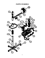
Page 21: ...21 PARTS DRAWING 104 121 115 114 113 320 112 119 337 327 104 336 6B 165 289 314 105 116A 120A 165 MDCSC13 MQAC12 309 311 285 362 312 390 310 315 283 304 286 313 389...

Page 22: ...22 NOTES...

Page 23: ...23 NOTES...

Page 24: ...MA SPORTS 200 Waterfront Drive Pittsburgh Pennsylvania 15222 Phone 800 333 0337 Fax 412 323 0317 Visit our website at www gammasports com Copyright 2014 GAMMA Sports All Rights Reserved MMU2 76 MG532...

Reviews: