background image

G

AMATRONIC 

E

LECTRONIC 

I

NDUSTRIES 

L

TD


MegaV2 250 Installation Guide, Release 2.2 


26 


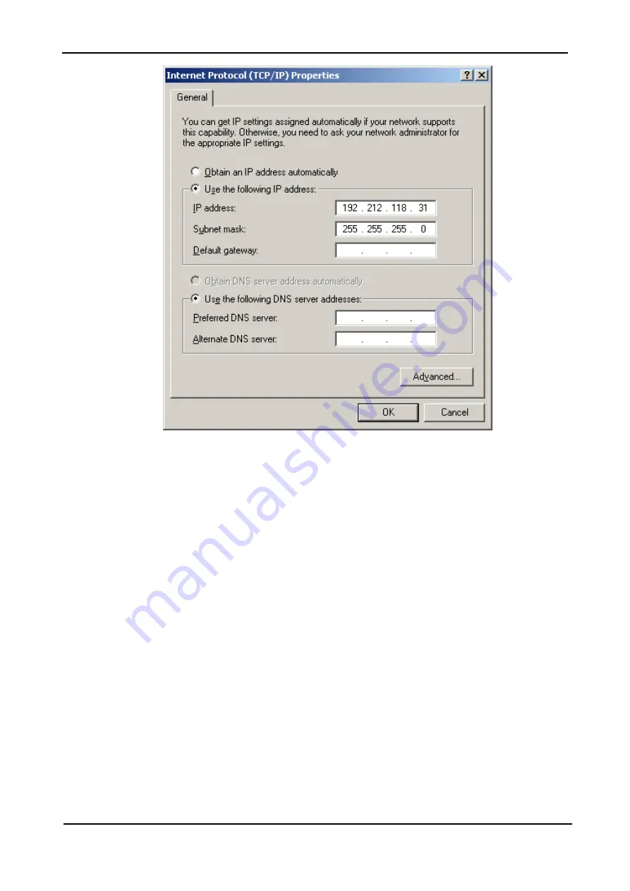
Figure 24:  Internet Protocol (TCP/IP) Properties screen 

d.  When the Internet Protocol (TCP/IP Properties screen appears, click the 

Use the 

following IP address 

button and enter 

IP address

 and 

Subnet mask 

in the 

appropriate fields. Leave 

Default gateway 

blank. Make sure that the first three groups 

of numbers in the IP address (192.212.118 in the above example) are the same as 
those of the domain in which the UPS is installed, and that the last number (31 in the 
above example) is different (it can be any number from 0 to 255, other than the one 
already assigned to the UPS).  

e.  Click 

OK 

twice to complete the network connection. 

3. 

Open your browser on your notebook and enter the IP address of the System 
Controller in the browser’s address field to verify that you can reach the Web server 
on the system controller. You should see the 

MegaV2 250

 main menu.


Summary of Contents for MEGA V2 250

Page 1: ...l 972 2 588 8222 Fax 972 2 582 8875 Email info gamatronic co il Website www gamatronic com 2MUM MPP 16 250 M MO OD DU UL LA AR R U UP PS S S SY YS ST TE EM M U UP P T TO O 2 25 50 0 K KW W Cat no 101S...

Page 2: ...Gamatronic is not responsible for any damage to the product due to unauthorized repair work misuse or abuse of the product or force majeure If the product is delivered without batteries Gamatronic is...

Page 3: ...1 2 7 Powering up the system 16 1 3 Initial configuration 17 1 3 1 Continuing first time start up process 22 1 3 2 Define the IP Address of MegaV2 250 23 1 4 Testing 24 1 4 1 Blackout Test 24 1 4 2 T...

Page 4: ...conditions 22 Figure 21 IP address configuration 23 Figure 22 Network Connections screen 25 Figure 23 Local Area Connection Properties screen 25 Figure 24 Internet Protocol TCP IP Properties screen 26...

Page 5: ...e 7 Technical specifications 56 STANDARDS AND CONVENTIONS This user manual contains diagrams which include images of the display screen of the UPS Unless otherwise indicated the readings shown in the...

Page 6: ...knowledgeable about national and local electrical codes and regulations Improper wiring may cause injury to personnel or death or damage to the equipment Pay attention to the warning signs labels and...

Page 7: ...ortation Do not connect or disconnect the cable to the battery cabinet before the battery circuit breaker is turned OFF Do not turn ON the battery circuit breaker when the battery cabinet is disconnec...

Page 8: ...GAMATRONIC ELECTRONIC INDUSTRIES LTD MegaV2 250 Installation Guide Release 2 2 viii...

Page 9: ...___________ 4___________5___________ 6___________ 7___________ 8___________ 9___________ 10___________ Technician Name Date Signature Operation Requirement Reference Visual Inspection Verify the physi...

Page 10: ...lled 1 2 4 1 Verify that the circuit breakers for the UPS ac input bypass input and output lines are in the OFF position Circuit breakers for ac input and output are OFF 1 2 4 3 Attach ac input bypass...

Page 11: ...vers 2 Ascertain that the number of modules delivered is as ordered and that a system controller module was delivered 1 2 2 Site Preparation Physical Perform the following procedures before connecting...

Page 12: ...is another UPS at the side of the MegaV2 the recommended clearance increases to 60 cm due to the additional heat generated by the second UPS However in the case that the two UPSs are being operated i...

Page 13: ...between L1 L2 L2 L3 and L3 L1 should be 3x400 Vac 10 Phase to neutral voltage measured at L1 L2 and L3 should be 230 Vac 10 5 Verify that voltage between neutral and ground is between 0 and 2 Vac 6 Ch...

Page 14: ...ve been threaded through the cable guard rear panel and have been connected to the UPS bus bars attach the cable guard item 2 in Figure 3 to the static switch s rear cover item 1 1 in Figure 3 Then at...

Page 15: ...to generator switching system you are in danger of having the neutral line disconnected when the four pole switch is operated This can result in the problems described above To avoid these problems w...

Page 16: ...e switch inside the cabinet 4 Verify that you obtain values of 360 Vdc red and 360 black with reference to N blue 5 With the battery box circuit breaker in the OFF position connect the battery box to...

Page 17: ...AMATRONIC ELECTRONIC INDUSTRIES LTD MegaV2 250 Installation Guide Release 2 2 9 Figure 4 Recommended standard system connections For recommended circuit breakers see Table 3 page 11 and Table 4 page 1...

Page 18: ...CTRONIC INDUSTRIES LTD MegaV2 250 Installation Guide Release 2 2 10 Figure 5 Recommended system connections with input isolation transformer For recommended circuit breakers see Table 3 page 11 and Ta...

Page 19: ...TCH SW1 MAIN CB CB1 WITH INPUT TRANSFORMER RECTIFIER CB CB2 BYPASS OUTPUT CBS CB3 CB4 CB5 CB6 25 3x63 A 3x40 A 3x40 A 3x40 A 50 3x100 A 3x80 A 3x80 A 3x80 A 75 3x100 A 3x100 A 3x100 A 3x100 A 100 3x16...

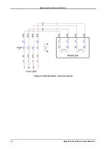
Page 20: ...GAMATRONIC ELECTRONIC INDUSTRIES LTD MegaV2 250 Installation Guide Release 2 2 12 Figure 6 Alternate battery connection option...

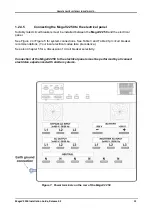
Page 21: ...electrical panel See Figure 4 or Figure 5 for system connections See Table 3 and Table 4 fpr circuit breaker recommendations Your local electrical codes take precedence See also Chapter 5 for a discus...

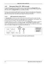
Page 22: ...test on the EPO switch before connecting it to the UPS 1 2 5 1 EPO indication for battery tripcoil The MegaV2 250 includes a dry contact that closes when the EPO switch has been activated This dry con...

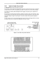
Page 23: ...trigger an external circuit in response to a system alarm The connections for the input and output dry contacts are located on the rear of the UPS on the external surface of the UPS above the main ter...

Page 24: ...ower modules If there are fewer than ten power modules in your system it does not matter which of the power module shelves you leave empty 2 Attach the LCD display screen to the module of your choice...

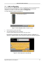
Page 25: ...on to enable initial operation of the MegaV2 250 The initial configuration process is described here Figure 12 Initial configuration wizard welcome screen 1 On the welcome screen press Start 2 The pas...

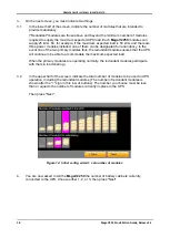
Page 26: ...two primary modules fails the redundant module ensures that the UPS will continue to be able to accommodate the maximum expected load When the primary modules are operating normally the redundant modu...

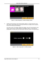
Page 27: ...t This capacity figure is used by the UPS when in battery mode to calculate the amount of backup time remaining If you are not sure of your battery cabinet s Ah capacity look at one of the batteries i...

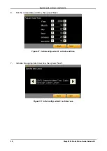
Page 28: ...gaV2 250 Installation Guide Release 2 2 20 6 Set the current date and time then press Next Figure 17 Initial config wizard set date and time 7 Indicate the appropriate time zone then press Next Figure...

Page 29: ...GAMATRONIC ELECTRONIC INDUSTRIES LTD MegaV2 250 Installation Guide Release 2 2 21 8 Press Finish to exit the wizard Figure 19 Finish configuration wizard Continue with section 1 3 1 below...

Page 30: ...indications Figure 20 The alarms icon indicates alarm conditions 6 Perform a brief battery test to verify that the MegaV2 250 is ready and able to operate in battery mode when needed To perform a bat...

Page 31: ...t DHCP 1 From the Main Menu select Setup Connectivity 2 Press the button labeled Obtain an IP address automatically The MegaV2 250 software obtains an IP address and then reboots itself To assign an I...

Page 32: ...not less that 2 below no load values 3 Check and record the total system load output current and make sure that MegaV2 250 is not overloaded with respect to system specifications 4 Verify that MegaV2...

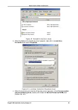
Page 33: ...the Network Connections screen appears right click on Local Area Connection and select Properties Figure 23 Local Area Connection Properties screen c When the Local Area Connection Properties screen...

Page 34: ...ree groups of numbers in the IP address 192 212 118 in the above example are the same as those of the domain in which the UPS is installed and that the last number 31 in the above example is different...

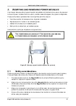
Page 35: ...QUIRES A TWO PERSON TEAM Figure 25 Moving a power module requires two persons 2 1 Safety considerations There are general principles of safety that apply to the insertion and removal of power modules...

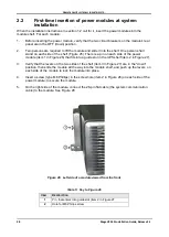
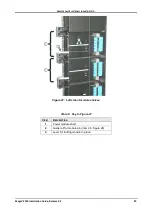
Page 36: ...the power module item 1 in Figure 26 that fits into a guide slot in the UPS shelf item 2 in Figure 27 3 Verify that the levers on the two sides of the shelf item 3 in Figure 27 are in the down positio...

Page 37: ...LTD MegaV2 250 Installation Guide Release 2 2 29 Figure 27 Left side of module shelves Table 6 Key to Figure 27 ITEM DESCRIPTION 1 Power module shelf 2 Guide rail for module pin item 2 in Figure 26 3...

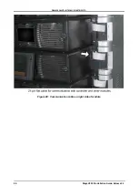
Page 38: ...GAMATRONIC ELECTRONIC INDUSTRIES LTD MegaV2 250 Installation Guide Release 2 2 30 Figure 28 Communication cable on right side of module...

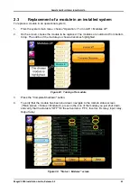
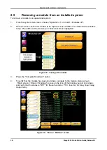
Page 39: ...to be replaced The modules are numbered from bottom to top The outline of the module you choose becomes highlighted Figure 29 Turning off a module 3 Press the Complete Shutdown button 4 To verify tha...

Page 40: ...up simultaneously on the two levers one on each side of the module 11 Secure the module with one screw on each side see item 2 in Figure 26 on page 28 12 Connect the flat cable module communication ca...

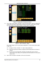
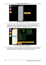
Page 41: ...system nominal value Figure 32 Status Modules Output If the output voltage of one or more phases is not within 2 of the system nominal output voltage then 19 1 Navigate to Setup Modules Ac output vol...

Page 42: ...allation Guide Release 2 2 34 21 Navigate to the main menu screen If the yellow triangular alarm indicator is visible check the alarms and see if any of them are related to the new module If there are...

Page 43: ...o place in the appropriate shelf Push the module all the way in and then push up simultaneously on the two levers one on each side of the module 3 Secure the module with one screw on each side see ite...

Page 44: ...e that was just switched on and verify that the status is ON for these five items PFC Inverter Dc relay Input relay Output relay Verify that the other fields are also normal Figure 35 Verifying status...

Page 45: ...acement module is within 2 of the system nominal value 11 Switch ON the output circuit breaker on the rear of the module 12 The MegaV2 250 controller must be informed that a new module has been added...

Page 46: ...be replaced The modules are numbered from bottom to top The outline of the module you choose becomes highlighted Figure 37 Turning off a module 3 Press the Complete Shutdown button 4 To verify that t...

Page 47: ...e of the module the other on the right side of the module Slowly pull the module out of the shelf Be prepared for the fact that when the module is pulled out about 15 cm its weight will no longer be s...

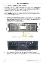
Page 48: ...in place in the MegaV2 250 frame and should be removed from a module before that module is removed from the MegaV2 250 frame 1 Open the small compartment on the center of the power module s front pan...

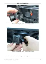
Page 49: ...IES LTD MegaV2 250 Installation Guide Release 2 2 41 Figure 41 Attaching the clamp to the mounting post part 1 Figure 42 Attaching the clamp to the mounting post part 2 3 Slide the LCD screen onto the...

Page 50: ...onto the mounting clamp 4 Now attach the communication power cable to the right rear side of the screen The cable should be visible projecting from the right side of the UPS s frame If not you will f...

Page 51: ...Figure 44 The screen s cable projects from right side of UPS frame There is a spring loaded catch on each side of the cable head Squeeze the catches press the cable head firmly and gently onto the LC...

Page 52: ...GAMATRONIC ELECTRONIC INDUSTRIES LTD MegaV2 250 Installation Guide Release 2 2 44 Figure 45 Attach comm cable to the LCD screen 5 Press the screen s power button to power on the screen...

Page 53: ...e MegaV2 250 from the front See the arrow in Figure 46 Figure 46 The MegaV2 250 Figure 47 The front left of the MegaV2 250 1 Open the hinged plastic door indicated by A in Figure 47 The metal panel in...

Page 54: ...GAMATRONIC ELECTRONIC INDUSTRIES LTD MegaV2 250 Installation Guide Release 2 2 46 Figure 48 The flat cables Figure 49 The power cord Figure 50 The left side of the computer...

Page 55: ...omputer box out of the MegaV2 250 6 Slide the new computer into the MegaV2 250 and connect the wires on the right side of the computer 7 On the left side of the computer connect the rightmost flat cab...

Page 56: ...B03 from tripping open before CB05 trips open Figure 52 A UPS s bypass circuit Selection of circuit breakers to achieve discrimination involves the consideration of two factors thermal tripping and ma...

Page 57: ...50 msec This ensures that the circuit breaker will interrupt the short circuit before any damage can be done to the static switch contactor and the UPS modules If you choose to use a time delay circui...

Page 58: ...should include a visual inspection of the UPS and its batteries and the tightening of any screws and bolts that have over time become loosened The owner of the UPS is responsible for ensuring that the...

Page 59: ...and physical condition The operation of the UPS and its batteries conform to design specifications The UPS and batteries are in compliance with all relevant safety standards and regulations It is reco...

Page 60: ...ot OK Comments ________________________________________________________ Environmental Inspection Environmental temperature ________ C Ventilation OK Not OK Air conditioning Yes No Comments ___________...

Page 61: ...of power to the load OK Not OK Comments ____________________________________________________ Inspect and Clean the Fans Grid Done Examine and clean the modules fans from the outside with a vacuom or...

Page 62: ...tor of 0 5 300 W rating recommended for the load to check the voltage drop across the terminals of each battery The voltage measured across the resistor should be no less than 10 Vdc for any battery R...

Page 63: ...customer and Gamatronic In regards to service oral agreements have no standing Service shall be provided gratis during the warrantee period on the condition that the UPS has been properly maintained...

Page 64: ...load Load CF max 6 1 Ac Ac efficiency nominal Up to 96 at full load Dc Ac efficiency nominal Up to 98 at full load Batteries Dc Link voltage 320 Vdc to 405 Vdc Quantity 60 12 V Type Sealed lead acid r...

Page 65: ...d on bypass Battery test failure Over under temperature Overload Each system alarm type can be routed to the dry contact of your choice Communication ports Serial Ethernet USB Communication protocols...

Page 66: ...ower systems for Telecom Dc to Ac Inverters Dc to Dc Converters Frequency Changers Battery Chargers Power Management Solutions Headquarters and Factory 17 Hartom Street POB 45029 Jerusalem 91450 Israe...

Reviews: