G
AMATRONIC
E
LECTRONIC
I
NDUSTRIES
L
TD
.
MegaV2 250 Installation Guide, Release 2.2
2
√
Operation
Requirement
Reference
Comments on site preparation
–
physical: __________________________________________
_______________________________________________________________________________
_______________________________________________________________________________
S i t e P r e p a r a t i o n – E l e c t r i c a l
Check size of circuit breakers on electrical boards
supplying the MegaV2 250. Refer to Chapter
5 in
this Installation Guide.
Meet local code and Gamatronic
recommendations.
1.2.3 Step 1
Check diameter of input and output power cables
connections, GND, and neutral lines. Refer to
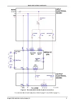
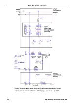
Figure 4 or Figure 5, Table 3, and Table 4.
Meet local code and Gamatronic
recommendations.
1.2.3 Step 2
Verify ac input voltages.
Phase-to-Phase: 3x400 Vac,
±10 %
Phase-to-Neutral: 230 Vac, ±10 %
1.2.3 Step 3
Verify the voltage between neutral and ground.
0–2 Vac
1.2.3 Step 4
Verify dc voltage at battery cabinet switch.
+360 V and – 360 V
1.2.3 Step 5
Verify that neutral is always connected.
Neutral connection will always be
unbroken during UPS operation.
Install the cable guard at rear of system.
Cable guard installed.
Verify that the circuit breakers for the UPS ac input,
bypass input and output lines are in the "OFF"
position.
Circuit breakers for ac input and
output are "OFF".
Attach ac input, bypass ac input, and output cables
to the MegaV2 250 (refer to Figure 4 or Figure 5).
Ac input, bypass, and output
cables are attached.
Assemble and connect the batteries within the
battery cabinet, verify proper voltage.
Batteries are assembled and
ready for operation or for
charging.
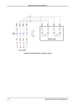
With the battery circuit breaker "OFF", connect the
battery cable to the UPS. Leave the battery circuit
breaker "OFF".
Batteries are connected and OFF.
Use a two-man team to insert the power modules.
The modules are heavy.
Two persons are required to insert
the power modules.
2
Attach the LDC display screen to one of the power
modules.
Screen is mounted on a module
and and cable connected to it.
3
Power-up the system.
LCD screen is on.
1
1.2.7
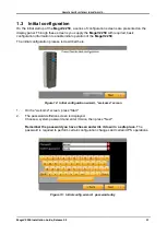
Perform the initial configuration.
Initial configuration completed.
Complete first-time startup.
First-time startup completed.
Perform post-startup tests.
Tests successfully completed.
Comments on site preparation
–
electrical: __________________________________________
_______________________________________________________________________________
_______________________________________________________________________________


