background image


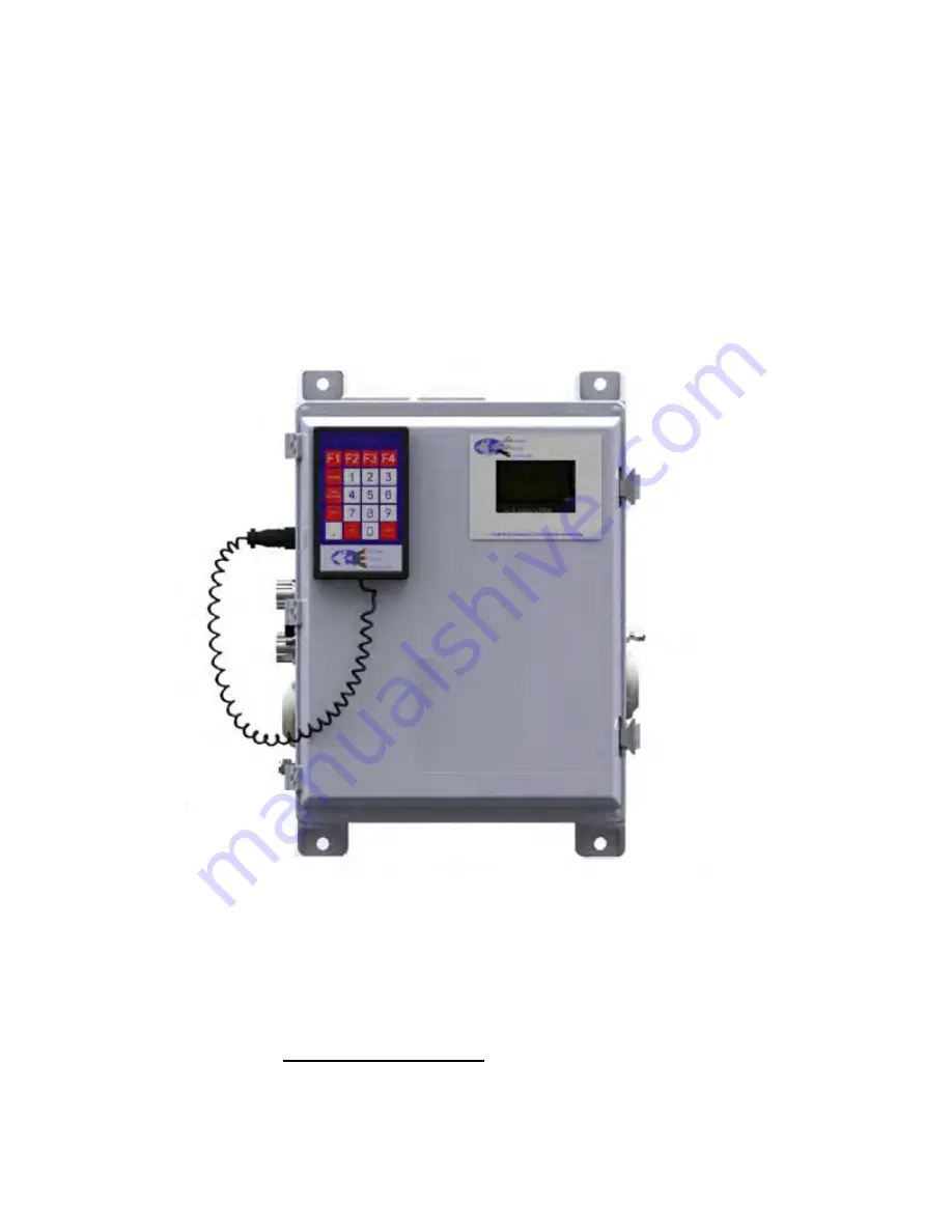
ProTech903W 


Phosgene Analyzer  


OPERATION MANUAL 


Revision 2 

May 27, 2015


Galvanic Applied Sciences, Inc. 

7000 Fisher Road S.E. 

Calgary, Alberta, T2H 0W3 

Canada 

Phone: (403) 252-8470 

Fax: (403) 255-6287


E-mail: [email protected] 

World Wide Web

http://www.galvanic.com


Summary of Contents for ProTech903W

Page 1: ...yzer OPERATION MANUAL Revision 2 May 27 2015 Galvanic Applied Sciences Inc 7000 Fisher Road S E Calgary Alberta T2H 0W3 Canada Phone 403 252 8470 Fax 403 255 6287 E mail info galvanic com World Wide W...

Page 2: ...this manual is subject to change without notice and does not represent a commitment on the part of Galvanic Applied Sciences Inc No part of this manual may be reproduced or transmitted in any form or...

Page 3: ...e up Reels 19 2 5 2 Pulse Counter 20 2 6 SAMPLE CHAMBER ASSEMBLY 21 2 6 1 Rate Read Aperture Strip and the Rear Window Assembly 22 2 6 2 Read Rate Aperture Strip 23 2 6 3 Sensor Block 23 2 6 4 Compres...

Page 4: ...48 4 3 3 Display Menus and Sub menus Descriptions 48 4 4 USING THE HANDHELD KEYPAD 49 4 5 THE STREAMS MENU 51 4 6 THE ALARMS PAGE 53 4 7 THE DISPLAY MENU 54 4 7 1 The SQNC Menu 54 4 7 2 IO Menu 54 4 7...

Page 5: ...tion Used 94 5 10 3 6 Alarms 94 5 10 4 Calibration Reference and Zero Gas Tabs 95 5 10 4 1 Calibration Tab 95 5 10 4 2 Reference Tab 96 5 10 4 3 Zero Tab 96 5 10 4 4 Differences between the Sample Tab...

Page 6: ...pes of Parameters in a Configuration 122 6 2 3 General Guidelines for Editing Parameters 122 6 3 COMMONLY EDITED PARAMETERS 123 6 3 1 The Streams Tab 123 6 3 2 Sequencer Tab 124 6 4 LESS COMMONLY EDIT...

Page 7: ...COMMONLY OBSERVED PROBLEMS 152 SECTION 9 ANALYZER Q C DOCUMENTATION 154 SECTION 10 PHOSGENE ANALYZER WIRING BOOK 157 SECTION 11 TECHNICAL SPECIFICATIONS 166 11 1 PERFORMANCE SPECIFICATIONS 166 11 2 FU...

Page 8: ...Revision 1 8 9 10 2019...

Page 9: ...The Warning symbol indicates a hazardous situation that if not avoided could result in death or serious injury The Caution symbol with the safety alert symbol indicates a hazardous situation that if...

Page 10: ...stem Disconnecting the main power source may not remove power from the analog output signals Any safety recommendations or comments contained herein are suggested guidelines only Galvanic Applied Scie...

Page 11: ...ity transportation charges prepaid or accept the return of the defective Product and refund the purchase price paid by Buyer for that Product If requested by Buyer Seller will use its best efforts to...

Page 12: ...e processor or software or firmware will be uninterrupted or error free The warranty herein applies only to Products within the agreed country of original end destination Products transferred outside...

Page 13: ...d on the tape The rate of colour change on the tape is directly proportional to the concentration of phosgene in the gas stream When the rate of colour change is measured the concentration of phosgene...

Page 14: ...and report generation Built in MODBUS communications RTU capabilities and a large number of outputs and inputs with sensor auto calibration on each analysis and dual redundant power supply 1 4 System...

Page 15: ...ion 6 Operating the System discusses the role of the various tabs of the how the various tabs of the Graphical User Interface are employed Section 7 Maintenance includes a discussion of activities whi...

Page 16: ...he analyzer is presented in Figure 2 1 Figure 2 1 Schematic of Flow Path The phosgene application does not use the bubbler shown in Figure 2 1 The system includes the following major components Mother...

Page 17: ...the analyzer uses the AC solenoid drivers which are Black in colour If a DC supply is used the analyzer uses the DC solenoid drivers which are Red in colour The analyzer can operate in a dual redundan...

Page 18: ...ctly under the LCD Display There are jumpers located on the bottom left hand corner of the CPU board that need to be set if this jack is to be used or if the Ethernet card is used The Ethernet Card op...

Page 19: ...e bottom of the chassis and can hold reels of tape up to 350 feet in length The tape is threaded over the lower tape guide past the sample chamber assembly and compression head over the two upper tape...

Page 20: ...uent stains tape wastage is minimized and tape life is maximized When the motor advances the take up reel causing the tape to move the movement of the tape causes the capstan on the pulse counter to r...

Page 21: ...measurement of the phosgene concentration in the gas The sample chamber assembly allows the sample gas to pass onto the sensing tape and also contains the detector assembly sensor block An exploded v...

Page 22: ...sensor block above it The rate read aperture strip is sealed to the inside of the sample chamber using silicone grease The sample flow through the sample chamber assembly is shown in Figure 2 6 Figur...

Page 23: ...equire an aperture strip Galvanic Applied Sciences provides a broad range of read rate aperture strip sizes The most common aperture strip sizes are listed in Table 2 1 along with the maximum ranges t...

Page 24: ...an be used to trigger alarms should the ambient temperature rise above or drop below set amounts values that can be set in the GUI The sensor block plays a key role in the tape advance algorithm While...

Page 25: ...ctor produces a positive pressure at the exhaust while allowing the analyzer vent to remain at ambient pressure An eductor is shown in Figure 2 1 Figure 2 10 Eductor The eductor has two purposes Chang...

Page 26: ...Sample Conditioning System Optional The sample conditioning system is an optional accessory that filters the sample gas and lowers it to a pressure suitable for use in the system A typical sample cond...

Page 27: ...Revision 1 27 9 10 2019 power vent The calibration valve can be either a manual 2 way valve or a solenoid controlled by the system...

Page 28: ...ower When choosing a power source the type of solenoid drivers need to be considered AC or DC 3 2 2 Location of the System The system is designed to be operated at ambient temperatures from 10 50oC Ga...

Page 29: ...a panel allow approximately 15 on the left hand side of to allow the removal of the tape cover on the side of the chassis and to allow easy access for tape installation and removal If the system is i...

Page 30: ...shipping container and remove all packing material and boxes Visually inspect the system and accessories package s to ensure that no damage has occurred If damage has occurred save all packing materia...

Page 31: ...or via a standard USB cable included with the analyzer The COM port used to connect to the system cannot be used for any other purposes otherwise connecting to the system will not be possible Display...

Page 32: ...it will go through a number of diagnostic protocols and display the results on the front panel display After about 1 minute the main screen will be presented Figure 3 4 Figure 3 4 The Main Analyzer S...

Page 33: ...cable included with the analyzer to the USB port to the right of the LCD display on the front of the analyzer between the labels Rx USB and Tx USB and connect the serial end of this cable to the male...

Page 34: ...m double click the GAS903 icon on the desktop Figure 3 6 Figure 3 6 GAS903 Software Icon Click on the Communications Settings button Figure 3 7 on the button bar of the application program to access t...

Page 35: ...munications Setup Dialog Box Figure 3 9 Communications Setup Window Modem Enter the number to be dialed by the modem if a 9 is required to access an outside line or a 1 is required to communicate with...

Page 36: ...t the Modbus Address field to the desired Modbus address valid range from 1 to 255 As an alternative put a checkmark in the All Stations checkbox which will cause the analyzer to poll all possible Mod...

Page 37: ...writing any changes to these settings Update mode allows the operator to make changes to settings in the application program and write these changes to the analyzer This mode is password protected to...

Page 38: ...t the keypad to the military connector on the left side of the chassis 3 5 2 Installing the Sensing Tape The sensing tape is installed in the tape enclosure Figure 3 13 presents shows a photo of the t...

Page 39: ...back and slide the tape behind the compression head Ensure that the tape is flat against the groove in the sample chamber 8 and has no creases e Pull the tape up over the upper sample chamber guide p...

Page 40: ...e retaining disks and the one on the right shows the tape installation with the disks Figure 3 15 Installation of Sensing Tape Using the keypad press F4 and then press F1 to access the Config Gen scre...

Page 41: ...have a good seal between the compression head the tape and the sample chamber To test the seal Galvanic recommends the use of a Dwyer Minhelic II gauge available from Galvanic Applied Sciences The ga...

Page 42: ...d ensure that the pressure does not drop below 3 even when the tape is moving It should return to 4 by the time the tape stops moving If the pressure is NOT 4 or greater there is a problem with the se...

Page 43: ...ibration gas of known concentration to the calibration port and perform a manual reference run Repeat this step for the second stream if applicable If the reading on the analyzer LCD screen is within...

Page 44: ...rsonal computer is provided as discussed in Section 5 The overall operation of the analyzer is controlled by the parameters that are resident in the analyzer When parameters are established via the ap...

Page 45: ...LED indicates that at least one alarm has been triggered BYPASS Yellow blinks This LED blinks yellow if the unit is in bypass mode WARNING Red solid Red blinks This LED is used for the following a If...

Page 46: ...most recent run Section 4 3 2 The bottom two lines present the definition of the soft keys of the hand held controller Section 4 3 3 Figure 4 2 The LCD Display Main Page The information presented by t...

Page 47: ...span calibration This code is seen on power up and during a user forced sensor calibration through the keypad IDLE The system is waiting for a measurement from the sensor This code is seen on power u...

Page 48: ...hanges as the operator selects a specific function as described in Sections 4 4 to 4 8 Table 4 3 LCD Main Screen Function Key Definitions F Key Code Meaning F1 STRM Stream menu Allows the operator to...

Page 49: ...lay to access the menus that present a variety of system parameters The keypad is shown in Figure 4 3 Figure 4 3 The Keypad The keypad includes 20 keys Eleven keys are used to enter numerical data 0 9...

Page 50: ...o Bypass mode Pressing this key again will exit Bypass mode TAPE ADVANCE Pressing this key will cause the analyzer to cease the current analysis advance the tape and begin a new cycle EDIT Pressing th...

Page 51: ...line is used to indicate if the Lock Stream alarm should be enabled for the phosgene measurement to change the setting press the EDIT button The operator will be prompted to enter the desired value a...

Page 52: ...ence 1 run To initiate the Reference 1 run press the EDIT button and press ENTER to toggle the status from OFF to ON The analyzer will run the Reference 1 run according to the setup of the Reference 1...

Page 53: ...ED Current RTC Battery Max Tape Advance Alarm Low Tape Alarm Tape Length Alarm Tape Movement Alarm Sensor Calibration Alarm Bypass DC Power Alarm AC Power Alarm Analog Input Alarms AI 1 Limit AI 1 Lim...

Page 54: ...quence is entered via the GUI Section 5 14 and indicates the order of measurements that occur during a cycle The sequence cannot be edited via the hand held keypad mV Run State Time 6 1S1 S1 115 AUTO...

Page 55: ...h analysis e g S1 SAMPLE 10 0 means that the last reading for phosgene was 10 ppm and cannot be edited mV Run State Time 6 1S1 S1 115 Analyzer Reading S1 SAMPLE 10 0 S1 REF1 6 7 S1 REF2 8 9 F1 F2 F3 F...

Page 56: ...that any latched alarms will not unlatch if they are still in the alarm condition L mV This field is used to set the mV on the display to corrected mV indicated by mV on the display or live uncorrecte...

Page 57: ...OL Edit F1 F2 F3 F4 PGUP Up Down PGDN Figure 4 13 The DIO Display The status of the items on this menu can be edited by pressing the EDIT key followed by the ENTER key Each item can be edited e g ther...

Page 58: ...he MSEQ Menu Manual Sequencer When MSEQ F4 is selected on the Configuration menu Figure 4 11 the MSEQ menu is presented A typical menu is shown in Figure 4 15 This menu allows the user to initiate man...

Page 59: ...discussion of the protocol to connect the two units is presented in Section 3 4 The Graphical User Interface GUI is a Windows based application program which provides the analytical results and allow...

Page 60: ...ox Figure 5 3 will be presented Figure 5 3 Select Mode Dialog Box c The Read Only option will allow the operator to view data parameters and analyzer settings but will not allow the operator to change...

Page 61: ...ection 5 2 2 The Upgrade Window option is used to install new software and is discussed in Appendix A c Others Menu The Others menu contains Update Mode used to change from Read Only mode to the Updat...

Page 62: ...nalyzer and can contain three possible values OFF LINE which means that the GUI is not connected to an analyzer READ ONLY which means that the analyzer is in Read Only mode and UPDATE which means that...

Page 63: ...Once Reads back all the data points on the current screen Pushing this button allows the user to check and ensure that any changes written to the analyzer have been accepted Synchronize Time Updates t...

Page 64: ...on has been saved to a file previously pressing this button will overwrite the existing configuration file If offline a saved configuration file needs to be opened before one can be saved Save Configu...

Page 65: ...WET Allows the operator to configure the four discrete Wet inputs of the analyzer Outputs Allows the operator to configure the behaviour of the relays solenoids and analog outputs Sequences Allows th...

Page 66: ...utton allows you to store and view your analyzer configuration and its behavior before you make a final decision If you switch the power off to the analyzer or perform a Reboot the analyzer will rever...

Page 67: ...Figure 5 7 is the default tab of the GUI and allows the operator to see the status of many facets of the analyzer all at a glance The GUI automatically polls the analyzer every three seconds causing...

Page 68: ...that takes the values of several past concentration readings of the same run type into account PAA Shows the live Predictive Alarm Analysis PAA dv dt gain Raw mV Shows the current raw photodiode dete...

Page 69: ...the current analysis reading if highlighted blue or the last reading when that stream was run A reference gas is used as a periodic calibration check and cannot change the gain Reference 2 The Referen...

Page 70: ...be configured from the GUI Section 5 16 Relays shows the current status of the six relays The circle beside each of the relay titles indicates the status A red colour means that the relay has been tri...

Page 71: ...e four wet discrete inputs on the electronics board These discrete inputs can be such things as remote calibration etc A red circle beside a discrete input label indicates that the particular discrete...

Page 72: ...e clock should the power fail or drops below a hard coded value It can also be triggered if an invalid time is detected Maximum Tape Advance The maximum tape advance alarm will be triggered if the mot...

Page 73: ...ion 5 17 5 6 3 Analysis Alarms The bottom half of the tab presents the analysis alarms for each of the streams Each stream has 6 available types of gas runs each with its own set of alarms High Alarm...

Page 74: ...rnative a previously saved archival record can be loaded by pressing the Read Archive from File button The archive on the analyzer is quite large so downloading data from the archive can take several...

Page 75: ...Archive indicia For more information on the various types of logs see Section 5 7 3 3 Timestamp shows the date and time when the data in a given row was obtained To the right of these grey columns are...

Page 76: ...The yellow boxes at either end of the plot adjacent to the dashed blue line above the average contain the numerical value of the average plus 1 standard deviation and the yellow boxes at either end o...

Page 77: ...rings up a dialog box that allows the user to set the minimum and maximum value for the y axis scale Print N A Prints the chart to the printer of the user s choice Copy to Clipboard N A Copies the cha...

Page 78: ...ish to display starting at a certain date and ending at a certain date Today shows only data obtained on the current date Yesterday shows only data obtained yesterday This Month shows only data obtain...

Page 79: ...s entered into the dialog box only data exactly equal to 1000 will be displayed Ending Digits When this operator is used in conjunction with a number the data will be filtered such that only data endi...

Page 80: ...o the clipboard to be pasted into another program e g Microsoft Excel Copy Image to Clipboard copies an image of the table to the clipboard that can be pasted into an image editing program or into a M...

Page 81: ...olumn The log can only be updated at the top of the hour Enter a value of 0 midnight to 23 11pm in this column Log Periodic 1 and 2 these two logs are empty by default when the analyzer is set up at t...

Page 82: ...l expand the node to show all of the data points within that node To put any data point into a log left click on the data point of interest and while holding the right mouse button down drag the data...

Page 83: ...full list of all of the Event Log records from the analyzer simply press the Read from Device button at the top of the screen Records in the Event Log can be sorted according to the date using the sa...

Page 84: ...y Usage This shows the percentage of the Event Log memory currently used by the Event Log When this number reaches 100 the analyzer will start writing over the oldest Event Log records with the newest...

Page 85: ...obal Alarms Section 5 9 2 Calibration Gain Calculator Section 5 9 3 Whenever any change is made to a changeable field the change must be written to the analyzer before leaving that page by pressing th...

Page 86: ...field under any circumstances unless instructed to by Galvanic service personnel Version The values in the three unchangeable fields in this box show the current versions of firmware installed in the...

Page 87: ...ime it makes one full revolution so dividing the circumference of the pulley in feet by the number of pulses per revolution will give the length of tape advanced when the pulse counter receives one pu...

Page 88: ...by default to 19mA for a Class I Div 2 unit The actual sensor LED current can be viewed on the Analysis tab High and Low temperature limits are set to 40oC and 0oC respectively Maximum Tape Advance Li...

Page 89: ...Revision 1 89 9 10 2019 5 10 Streams Tab 5 10 1 Overview The Streams tab Figure 5 19 is used to configure the analyzer to perform the desired analyses Figure 5 19 Stream Tab Sample Tab...

Page 90: ...for Sample for stream 1 is being edited The system described in Figure 5 19 and 5 20 includes screens which can be edited The three parameters and three check boxes on the left of the tab are univers...

Page 91: ...is not checked then the calibration run is essentially another reference run Zero Correction Enable check box used to indicate if the zero gas run to change the zero offset If this box is not checked...

Page 92: ...alysis algorithm used will depend on the analyzer s specific application and is set up at the factory The type of algorithm used and the sample delay and interval values should not be changed without...

Page 93: ...section Figure 5 23 of the gas run type tab The drop down Day of Week list includes Everyday and each day Sunday to Saturday Figure 5 23 The Frequency Field 5 10 3 4 Analog Output Override If an Analo...

Page 94: ...lyzer compares the final calculated concentration at the end of the sample interval with the alarm 1 set point value If the value of the calculated concentration is higher than the alarm set point val...

Page 95: ...th PAA will return to their non triggered state Any latched outputs associated with this alarm will have to be manually cleared through the GUI High High Alarm Duration The number of seconds entered i...

Page 96: ...tion run triggered from the GUI will be put into the run queue and not run until the alarm condition s has have cleared 5 10 4 3 Zero Tab The Zero run provides a way to check what the analyzer reads o...

Page 97: ...the Stream Calibration Used field The Alarms field contain only the High Alarm Enable and Deviation Enable options Runs to Average indicates the number of consecutive runs to be averaged to obtain th...

Page 98: ...type of run or to monitor external pressure or temperature switches for example Each discrete input is configured in the same manner It is important to know that these dry contacts are for devices tha...

Page 99: ...d and will not respond to any inputs If the Alarm checkbox is checked the condition of each discrete input will be logged in the Event Log 5 11 3 Polarity If the Active On radio button is selected the...

Page 100: ...for these inputs is 4 24 VDC The Inputs WET tab allows the user to configure these discrete inputs in any manner These inputs can be configured to trigger a certain type of run or to monitor external...

Page 101: ...ny changes should be performed by an authorized operator The Output tab Figure 5 28 allows the user to configure the behavior of the six onboard relays 8 solenoids and 6 analog outputs The Output tab...

Page 102: ...til the user clears the latch regardless of whether or not the event that triggered the output has cleared Latch State The state of a latch is indicated by the coloured circle under the title Latch St...

Page 103: ...r tab Figure 5 29 is used to generate the analyzer gas run sequences or indicate that manual operation is desired Figure 5 29 Sequencer Tab The Sequencer tab is divided into three main areas Available...

Page 104: ...e gas stream 5 14 2 Available Run Types A list of all the types of gas runs listed under each stream is provided on the left side of the tab To setup a sequence of gas runs click on the desired gas ty...

Page 105: ...ng performed To remove an item from the sequence list click on it to highlight the line blue and use the Delete Key on the keyboard 5 14 4 Manual Sequencer Request Checkbox The Manual Sequencer Reques...

Page 106: ...by checking the Run checkbox for any particular manual sequence The Loop Enable checkbox can also be checked to allow the manual sequence to run indefinitely The Run and Loop Checkboxes can be ignored...

Page 107: ...e configuration of the three communications ports on the analyzer the Front Panel Serial Port RS 232 the ISO 485 Port RS 485 and the MODEM Port RS 232 Figure 5 32 Ports Tab This tab is used to configu...

Page 108: ...s and every user may desire a slightly different configuration this manual will only cover the basics of Modbus configuration If the user requires assistance in setting up a Modbus configuration the S...

Page 109: ...Revision 1 109 9 10 2019 Figure 5 34 Create Modbus List Dialogue Box...

Page 110: ...n with Floating Point will read MODICON32 The other field is called Address and the user must input the desired Modbus address for the analyzer into this field 5 16 1 Enron An Enron Modbus list contai...

Page 111: ...tely These would include such things as tape length calibration gas concentration and gain factor 5 16 3 Modicon with Floating Point Just like the Modicon 16 Modbus list the Modicon with Floating Poin...

Page 112: ...Revision 1 112 9 10 2019 Figure 5 36 Typical Modcon with Floating Point List...

Page 113: ...data entry fields six results fields and three initiate buttons which are described below Analog Input 1 2 and 3 are normally setup as default 4 20 mA inputs but all the inputs can be scaled to what...

Page 114: ...riate values can be entered Capture Zero used to capture the A D bits that are associated with a 4mA input during the calibration of the analog input Scaled Zero used to enter the zero value or the ra...

Page 115: ...and stop timer set points Figure 5 40 Timers Tab It is important to note that any conditional events will only commence after the previous run is completed For example if a Zero gas run is scheduled t...

Page 116: ...tever is scheduled in that column to run every hour 5 18 2 Analysis The Enable checkbox must be checked before any of the gas runs listed below can be executed on a timer For any of the analysis types...

Page 117: ...puts and test the operation of any of the relays or solenoids under direct board control This feature is useful during analyzer commissioning Figure 5 41 Maintenance Tab Changing Parameters in the Mai...

Page 118: ...k red notifying the user of this condition Direct board control will automatically be disabled if the user changes to any other screen in the GUI However it will not automatically be disabled should t...

Page 119: ...utton Next press the Auto Cal button located below the Meter Reading Field This will cause the analog output to be calibrated to exactly 4 mA d Once the multimeter does read this exact value press the...

Page 120: ...120 9 10 2019 5 20 Factory Tab The Factory tab Figure 5 43 is password protected All the parameters on this tab is set in the factory and should only be changed by authorized personnel Figure 5 43 Fa...

Page 121: ...n connected to the personal computer and the Update mode all input and output devices have been interfaced In this chapter we will simply point out how each tab in the application program fits into th...

Page 122: ...yzer button Figure 6 1 or the Permanent Configuration Write to the Analyzer button Figure 6 2 Figure 6 1 Write Current Page to Analyzer Button Figure 6 2 Permanent Configuration Write to the Analyzer...

Page 123: ...amples can be analyzed analytical samples reference samples calibration samples zero samples The Stream tab Figure 6 3 is used to enter information about each type of sample timing information and ala...

Page 124: ...er tab Figure 6 4 is used to create analyzer gas run sequences The user can set up the analyzer gas run sequences to initiate either automatically or manually A detailed discussion of the Sequencer ta...

Page 125: ...are set when the analyzer is initially installed and once they are set they are infrequently edited 6 4 1 The Global Tab The Global tab Figure 6 5 used to establish a broad range of system related pa...

Page 126: ...gure 6 6 and Inputs DRY tab are identical and allow the operator allows the user to configure these discrete inputs in any manner These inputs can be configured to trigger a certain type of run or to...

Page 127: ...re the behaviour of the 6 onboard relays and 8 solenoids In addition it is where the analog outputs are named and configured The tab is divided into 2 main sections Digital Output and Analog Outputs A...

Page 128: ...gure 6 8 shows the configuration of the 3 main communications ports on the analyzer the Front Panel Serial Port RS 232 the ISO 485 Port RS 485 and the MODEM Port RS 232 A detailed discussion of the Po...

Page 129: ...number of possible configurations for Modbus and every user may desire a slightly different configuration this manual will only cover the basics of Modbus configuration If the user requires assistance...

Page 130: ...ers another powerful way to trigger conditional gas run requests other than the ones on the Streams Tab Manual Sequences can also be triggered using start and stop timer set points A detailed discussi...

Page 131: ...er s outputs Analog output loop test can be performed by using the Analog Output Test feature to deliver 0 25 50 75 and 100 of full scale or any other test values The outputs can also be adjusted by u...

Page 132: ...analyzer can be in Reference Mode While the analyzer is in Reference Mode any data will be logged as Reference data not as stream data To place the analyzer in reference mode using the GUI software to...

Page 133: ...of the analyzer Set the output pressure of the calibration standard to the same pressure that the sample gas normally runs at this is typically 15 psig c Turn the 3 way valve to introduce calibration...

Page 134: ...4 and F3 keys to scroll down to CAL It will currently indicate that the status is OFF Press the EDIT key on the keypad and press the ENTER key to toggle the value to ON Figure 6 12 Initiate Stream Cal...

Page 135: ...Revision 1 135 9 10 2019 When an Auto Calibration is initiated either from the GUI or from the keypad the analyzer will finish the current analysis cycle before it begins the calibration cycle...

Page 136: ...lows the operator to see the status of many facets of the analyzer all at a glance The GUI polls the analyzer every 3 seconds causing this information to be updated continuously A detailed discussion...

Page 137: ...ad Archive from File button The archive on the analyzer is quite large so retrieving data from the archive can take several minutes especially if the PC is connected to the analyzer via a serial conne...

Page 138: ...log of all operations that occur during operation and is a useful way to monitor the system It tracks all alarm conditions experienced by the analyzer both global and stream related but also such thi...

Page 139: ...9 9 10 2019 Figure 6 16 The Events Tab The Alarms tab Figure 6 17 allows the operator to view the status of most of the enabled analyzer alarms A detailed discussion of the Alarms tab is presented in...

Page 140: ...ent status of the analog outputs relays solenoids Analog inputs Discrete inputs and what voltage input source is in use In some cases the activation or deactivation of the status indicators may sugges...

Page 141: ...Revision 1 141 9 10 2019 Figure 6 18 Status Tab...

Page 142: ...7 2 Routine Maintenance Procedures a Check display for any alarms press F2 on keypad See Section 8 for information about resolving any active alarms b Disable alarms by pressing the BYPASS button c Tu...

Page 143: ...on an alarm will be presented on the Alarms tab of the GUI and the hand held controller when the tape level is low To replace the tape a Check the hand held display for any alarms b Disable alarms by...

Page 144: ...side of the reel not the right g Thread the tape over the lower sample chamber guide pin 3 Push the compression head 4 back and slide the tape behind the compression head Ensure that the tape is flat...

Page 145: ...the tape reel on the supply reel clockwise until the tape is tight The correct installation of tape on the analyzer is shown in Figure 7 4 The image on the left shows the completed tape installation w...

Page 146: ...of the cycle q Reset the tape length to 300 ft through the keypad 7 4 Checking the Sample System On a periodic basis the sampling system should be inspected and cleaned to ensure an optimum flow of s...

Page 147: ...factory assistance on the analyzer For Service and or Assistance Contact Galvanic Applied Sciences Inc 7000 Fisher Road SE Calgary Alberta T2H 0W3 Canada Tel 403 252 8470 TOLL FREE CANADA US 1 866 252...

Page 148: ...AC Power Alarm Analog Input Alarms AI 1 Limit AI 1 Limit AI 2 Limit AI 2 Limit AI 3 Limit AI 3 Limit AI 4 Limit AI 4 Limit Analysis Alarms Sample High Alarm High High Alarm Deviation Lock Analysis Al...

Page 149: ...the analyzer and when exactly they occurred To obtain a full list of all of the Event Log records from the analyzer simply press the Read from Device button at the top of the screen 8 3 Alarms Tab The...

Page 150: ...date in the real time clock varies from the time and date of the connected PC by more than a certain amount Maximum Tape Advance Triggered if the motor advances the tape more than a certain number of...

Page 151: ...exceptionally dark before the next analysis begins or if there is no tape present Bypass Bypass mode is a mode of the analyzer that disables any outputs that may be triggered by alarms and is typical...

Page 152: ...rratic readings Compression head not correctly sealing Check the seal on the compression head Tape not seated properly Remove tape and reinstall tape 5 Stain is uneven darker at top or bottom causing...

Page 153: ...the Output tab of the GUI 10 Calibration Reference or zero runs are not running after being initiated by keypad or schedule System in Alarm 1 or PAA condition on Sample Run Wait until alarm condition...

Page 154: ...ure that the system meets all manufacturing specifications and is built to meet the customer s specific requirements This chapter consists of the form which provides the overall QA procedure and shoul...

Page 155: ...g Chassis Flow Meter BA0328 T S Flow Meters BA0071 Auto Cal Solenoid Yes No Flow Meters Set Up Sample Set At 0 5 On Tube Scale Global Setting Area Classification Class I Div 2 Groups B C D Class I Div...

Page 156: ...or Reference 1 Run mV TSC mV for Reference 2 Run mV TSC mV for Zero Run mV High Alarm Enabled Relay Solenoid Deviation Enabled Relay Solenoid High High Alarm Enabled Relay Solenoid High High Alarm Dur...

Page 157: ...External Furnace P1 P2 P3 P5 10 3 AC DC Power P3 P4 P5 10 4 Solenoid Drivers P5 P6 10 5 Relays Wiring P7 P8 10 6 Digital Inputs Isolated P9 10 7 Digital Inputs Dry P10 10 8 Isolated 4 20 mA Outputs P1...

Page 158: ...Revision 1 158 9 10 2019 Figure 10 1 DC Power Wiring Diagram Figure 1010 2 AC Power Wiring Diagram...

Page 159: ...Revision 1 159 9 10 2019 Figure 10 3 External Furnace Wiring Diagram Figure 10 4 AC DC Power Wiring Diagram...

Page 160: ...Revision 1 160 9 10 2019 Figure 10 5 Solenoid Drivers Wiring Diagram Figure 10 6 Relays Wiring Diagram...

Page 161: ...Revision 1 161 9 10 2019 Figure 10 7 Discrete Inputs Isolated Wiring Diagram Figure 10 8 Discrete Inputs Dry Contact Wiring Diagrams...

Page 162: ...Revision 1 162 9 10 2019 Figure 10 9 Isolated 4 20 mA Outputs Wiring Diagram Figure 10 10 Isolated 4 20 mA Inputs Wiring Diagram...

Page 163: ...Revision 1 163 9 10 2019 Figure 10 11 5V and 24 V Stepper Motor Wiring Diagram Figure 10 12 Isolated 2 5 Mbits LAN Expansion Port...

Page 164: ...Revision 1 164 9 10 2019 Figure 10 13 Isolated RS 485 Port Figure 10 14 P17 RS232 Port to Ethernet Cable...

Page 165: ...Revision 1 165 9 10 2019 Figure 10 15 Sensor Block Keypad Encoder and Low Tape Sensor Div 2 Wiring Diagram Figure 10 16 Non Isolated 4 20 mA Inputs...

Page 166: ...ycle time is user configurable typical 4 min 11 2 Functions Streams One includes Sample analysis run zero run reference1 run reference2 run calibration run and Multi Range Each stream can have separat...

Page 167: ...7 more optional 1 USB port 1 RS 232 Serial Port 1 RS 485 isolated serial Port 1 LAN Port for extended analog outputs 1 Ethernet optional Modbus communication on all ports Inputs 8 discrete inputs 4 Dr...

Page 168: ...verter equipped with temperature monitor on sensor block Sensor automatically calibrates on every cycle to prevent drift Optical tape counter optimizes tape usage and provides exact measurement of tap...

Page 169: ...e maintenance and service procedures Spare Parts can be obtained from Galvanic Applied Sciences 7000 Fisher Road S E Calgary AB Canada T2H 0W3 Main 1 403 252 8470 TOLL FREE CANADA US 1 866 252 8470 FA...

Page 170: ...FLOWMETER ROTOMETER W ADJUSTABLE KNOB FOR STANDARD ANALYZER BA0328 FLOWMETER ROTOMETER WO ADJUSTABLE KNOB FOR STANDARD ANALYZER BA1367 PERM DILUTION TUBE GP506 GENIE MEMBRANE PROBE FILTERS GP 506 PACK...

Page 171: ...Revision 1 171 9 10 2019...

Page 172: ...Revision 1 172 9 10 2019 Section 13 MSDS Information...

Page 173: ...114 B Backlight Lock On 95 BYPASS 59 Bypass Alarm 82 C Cal Gas Concentration 107 Cal Correction Enable 101 Calibrate A I 125 Calibrating Analog Outputs 130 Calibrating the Analyzer Outputs 142 Calibra...

Page 174: ...Factor 101 Gas Requirements 35 General Toolbar 73 Global Alarms 81 94 98 Global tab 94 Graph Format 84 Graphical User Interface 14 68 GUI 14 68 H Help Menu 71 High Alarm 60 High Alarm Enable 104 High...

Page 175: ...of Operation 13 Print Orientation 86 Print Sizing 86 Problems Commonly Observed 165 Pulse Counter 20 Purge Time 96 Purging 56 Q Q C Documentation 167 Quartz Tube Replacing 157 R Rate Read Aperture Str...

Page 176: ...Menu 60 Streams Tab 99 STRM 57 Supply and Take up Reels 19 Switching Field 103 Synchronize Time 72 System Menu 70 T TA 56 Table Format 83 Tabs 73 Take up Reels 19 TAPE 65 Tape advance 56 Tape Advance...

Reviews: