RG66001652_REV.02
21
LCW - LCR
3. Vacuum cycle
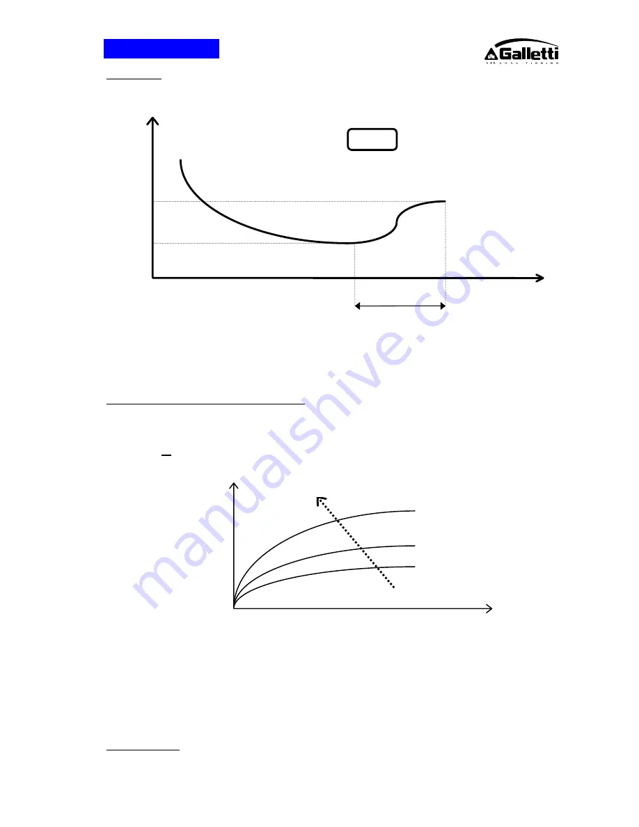
In general it is preferable to apply a “long” rather than “hard” vacuum: reaching low pressures too abruptly may in
fact cause any trapped humidity to evaporate instantaneously, thereby freezing part of it.
The figure represents a vacuum cycle and an optimal subsequent pressure rise for the refrigeration devices we
manufacture.
As a rule, if there is suspicion of an extensive presence of humidity throughout the circuit or system as a whole,
the vacuum must be “broken” with anhydrous nitrogen and then the steps must be repeated as described; this
operation facilitates the removal of trapped and/or frozen humidity during the evacuation process.
4. Evacuating a circuit “contaminated” with refrigerant
The first step is to remove the refrigerant from the circuit using a specific machine with a dry compressor for
recovering the refrigerant.
Refrigerants
all
tend to dissolve in oil [compressor sump] in percentages that are directly proportional to increases
in pressure and decreases in the T of the oil itself - Charles' Law -
The release of refrigerant tends to cool the oil and thus actually serves to oppose the release itself: for this
reason, it is advisable to switch on the crankcase heating elements, if available, during the evacuation process.
If a high % of refrigerant comes into contact with the Pirani gauge (vacuum sensor), it may “drug” the sensitive
element of the latter. rendering it inefficient for a certain period of time. For this reason. if no machine for
recovering refrigerant is available. it is nonetheless advisable to switch on the crankcase heating elements and
avoid applying a vacuum until the circuit has been adequately purged of refrigerant: the refrigerant may in fact
solubilise in the oil of the vacuum pump. undermining its performance for a long time (hours).
5. Charging positions [single point]
P [Pa]
Time
200 s
6
150
T1
T2
T3
Fig. 3
Oil T
Pressure
% of R.... in oil


