background image

IPE2500A and IPE2500-MLS Paging Encoder/Desktop Controller 

Table of Contents


03/12 Pub. 

43004-008H 

v


DTMF/H.E.A.R.


F

UNCTIONS

 ................................................................................................................................... 43


A

UDIO 

A

CCESSORY

/RS-232


P

ORT

 ........................................................................................................................... 43


M

ICROPHONE 

S

ENSITIVITY 

A

DJUSTMENTS

 ............................................................................................................... 44


Internal Microphone ........................................................................................................................................... 44


Handset Microphone ........................................................................................................................................... 44


Accessory Microphone ........................................................................................................................................ 44


L

EVEL 

A

DJUSTMENTS AND 

D

IAGNOSTICS

 ................................................................................................................. 45


Main Diagnostics Selection ................................................................................................................................ 45


Programming Menu ............................................................................................................................................ 45


Reloading Factory Defaults ................................................................................................................................ 47


PB1 – Line Output Adjust ................................................................................................................................... 47


PB2 - Line-In Sensitivity ..................................................................................................................................... 49


PB3 – Internal Diagnostics ................................................................................................................................. 50


PB4 – Tone Level Adjust ..................................................................................................................................... 53


CTL-PB1– Toggle Compressors ......................................................................................................................... 54


THEORY OF OPERATION .................................................................................................................................... 55


G

ENERAL 

D

ESK 

S

ET 

O

VERVIEW

 ............................................................................................................................... 55


R

ECEIVE 

A

UDIO

 ....................................................................................................................................................... 55


S

PEAKER 

A

UDIO

 ....................................................................................................................................................... 55


T

RANSMIT 

A

UDIO

 ..................................................................................................................................................... 56


M

ICROPHONE 

A

UDIO

 ................................................................................................................................................ 56


G

UARD 

T

ONE 

D

ETECTION

 ........................................................................................................................................ 56


DC


C

ONTROL 

M

ODULE 

(

NOT COMPATIBLE WITH 

MLS

 OPERATION

) ......................................................................... 57


R

ELAY 

C

ONTROL 

M

ODULE 

(

NOT COMPATIBLE WITH 

MLS

 OPERATION

) ................................................................... 57


M

ULTI

-L

INE 

S

ELECT 

M

ODULE

 ................................................................................................................................. 58


R

ESET 

C

IRCUIT

 ......................................................................................................................................................... 58


CARD SUITE PROGRAMMING SOFTWARE .................................................................................................... 59


G

ENERAL 

D

ESCRIPTION

 ............................................................................................................................................ 59


C

ONNECTION

 ............................................................................................................................................................ 59


I

NSTALLATION

 .......................................................................................................................................................... 59


R

EADING THE 

U

NIT

 .................................................................................................................................................. 59


CARD


S

UITE 

P

ROGRAMMING

 .................................................................................................................................. 60


Editing Screen ..................................................................................................................................................... 60


TROUBLESHOOTING ............................................................................................................................................ 61


T

ROUBLESHOOTING THE 

IPE2500A


D

ESK 

S

ET

 ........................................................................................................ 61


F

USE 

R

EPLACEMENT

 ................................................................................................................................................ 62


CIRCUIT BOARDS .................................................................................................................................................. 63


SCHEMATICS .......................................................................................................................................................... 67


DEFINITIONS AND ACRONYMS ......................................................................................................................... 81


Summary of Contents for IPE2500A

Page 1: ...540 USA 610 777 1374 800 492 1212 Fax 610 796 5954 VISIT WWW GAI TRONICS COM FOR PRODUCT LITERATURE AND MANUALS G A I T R O N I C S C O R P O R A T I O N A H U B B E L L C O M P A N Y IPE2500A and IPE...

Page 2: ...t shall GAI Tronics warranty obligations with respect to services exceed 100 of the total cost of services provided hereunder Limitations Exclusions The warranty on any equipment supplied hereunder is...

Page 3: ...A R SYSTEM SUPPORT 8 ACCESSORIES 9 FIELD REPLACEMENT ITEMS 9 PROGRAMMING 9 PERFORMANCE SPECIFICATIONS 10 OPERATION 11 DISPLAY 11 RECEIVING CALLS 12 INITIATING CALLS 12 Handset Transmit 13 Transmit Fr...

Page 4: ...ct DTMF Dialing 32 PTT Controlled Direct DTMF Dialing 32 Direct DTMF Dialing Using Immediate DTMF Paging 33 Audio Transmissions during Direct DTMF Dialing 33 Enabling Direct DTMF Dialing 33 RS 232 INP...

Page 5: ...s 50 PB4 Tone Level Adjust 53 CTL PB1 Toggle Compressors 54 THEORY OF OPERATION 55 GENERAL DESK SET OVERVIEW 55 RECEIVE AUDIO 55 SPEAKER AUDIO 55 TRANSMIT AUDIO 56 MICROPHONE AUDIO 56 GUARD TONE DETEC...

Page 6: ...Table of Contents IPE2500A and IPE2500A MLS Paging Encoder Desktop Controller 03 12 Pub 43004 008H vi...

Page 7: ...he factory for repair Please call 1 800 492 1212 to obtain a Return Authorization number published repair prices and shipping instructions A Return Authorization number can also be obtained by visitin...

Page 8: ...e avoid carpeted areas dry environments and certain types of clothing silk nylon etc because they contribute to static build up Similarly disconnect the test probe prior to removing the ground lead 5...

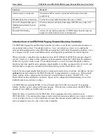
Page 9: ...parallel Each desk set operator knows the selected frequency Local DC E M E M with tone control Offers flexibility in types of remote and local control requires options to be installed Line Operated T...

Page 10: ...can be programmed using the CARD Suite Programming Software for specific control needs The multiple frequency control two line LCD display aliasing functions intercom parallel status updating programm...

Page 11: ...transmitter If using the handset it is not necessary to press the handset PTT The IC button will serve as the PTT Other desk sets in parallel will hear the audio automatically KeypadButtons The numeri...

Page 12: ...ed to allow hands free communication Handset Each desk set is equipped with a handset with a coil cord used for receiving and transmitting calls The handset includes a push to talk PTT pressbar Connec...

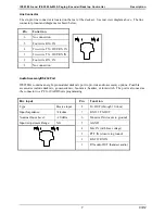
Page 13: ...on AudioAccessory RS 232Port IPE2500A contains an eight pin modular desk mic port to provide audio accessory options Possible accessories include desk mic gooseneck mic boom mic headset or footswitch...

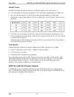
Page 14: ...he tone panel When the monitor CTCSS disable is activated the HLGT is generated for 120 ms then a function tone of 2050 Hz is generated for 40 ms Tone Levels Assuming that the ITA2000A Tone Remote Ada...

Page 15: ...oiled Cord with PTT for XHS003C requires XAAB002A XCC003C External Speaker Kit Unselect Audio for MLS XAC0120A Field Replacement Items Description Part No PTT Handset with Cord Black HANDSET BLACK Rep...

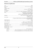
Page 16: ...15 Sub B Verification Canada ICES 003 Line Interface FCC Part 68 Exempt Category II Tariff 260 service for private leased line applications Canada IC CS03 8 Nominal input level 10 dBm Nominal output...

Page 17: ...ming Software section of this manual Display The IPE2500A has a backlit 2 16 character super twist LCD display to provide valuable operator information This information allows the operator to determin...

Page 18: ...ker in addition to the handset Initiating Calls Before initiating a call press the MONITOR button to verify that the radio channel is clear The MONITOR button remains illuminated until a transmit func...

Page 19: ...s can be keyed to transmit with an external desk microphone through the audio accessory port When a PTT signal is asserted through this port TX audio will also originate through this port Use of the G...

Page 20: ...de to scroll through the pre programmed paging aliases and for programming microphone sensitivity PB1 PB2 PB3 andPB4ProgrammableButtons The four programmable buttons with LED indicators are used to cu...

Page 21: ...are for parallel units to hear intercom audio MONITORButton When the MONITOR button is pressed the desk set adapter and the radio are placed in the monitor mode CTCSS CDCSS disabled the MONITOR LED il...

Page 22: ...isor tone the supervisor function will be decoded To illustrate the priorities of the decode function are as follows Highest priority Monitor Function Tone Supervisor On Function Tone Supervisor Off F...

Page 23: ...ress SELECT to select the frequency and exit the frequency selection mode Press MONITOR to select the frequency exit frequency selection mode pause 250 ms and send a monitor burst to monitor the newly...

Page 24: ...ervisor using a relay programmable button Hard SupervisorControl To ensure parallel units are locked out of transmission upon demand by the supervision position the relay I O module should be used and...

Page 25: ...ms During H E A R operation the internal speaker of the IPE2500A would typically be muted so that normal radio traffic is not heard in the emergency room A DTMF sequence is transmitted prior to voice...

Page 26: ...the radio is connected directly to desk set units on site the unit must be configured for local control Also a PTT and monitor relay must be programmed with the CARD Suite and these connections must...

Page 27: ...2500A via the XMLS001A 4 Line Field Install Kit The features include Tone remote control of two to four different base stations Vox detect indication for each line Unselect audio reference adjustment...

Page 28: ...n or set the base station in monitor Since parallel status updating is not possible in the IPE2500 MLS the operator should ensure that when selecting a line that the desired frequency is set Unselect...

Page 29: ...ion of the summed unselect audio This allows the unselect audio to remain in the background when both select and unselect audio are both present To adjust the unselect audio 1 Enter the Line Selection...

Page 30: ...r determined names to be assigned to specific paging capcodes This permits selecting a frequently used paging sequence by name rather than by re entering digits on the keypad EnteringthePagingMenu Mak...

Page 31: ...MONITOR to make sure the radio channel is not in use If programmed with an auto channel selection the unit selects that channel before sending the monitor control When the channel is free press TRANSM...

Page 32: ...equency Chart Group and indicates which row of frequencies on chart will be used for the B tone In this example the B tone number entered by the console operator is 3 which corresponds to 669 9 Hz The...

Page 33: ...2 3 4 5 6 7 8 9 Gen Enc 42 11 22 12 44 55 21 45 54 24 Gen Enc Modified 42 11 22 33 44 55 66 DD EE FF B N A 11 22 33 12 13 21 31 23 32 C N A 11 22 12 44 14 21 41 24 42 D N A 11 22 12 15 55 21 51 25 52...

Page 34: ...67 4 810 2 855 5 903 2 5 6 1122 5 1153 4 1185 2 1217 8 1251 4 1285 8 1321 2 1357 6 1395 0 1433 4 6 A 358 9 398 1 441 6 489 8 543 3 602 6 668 3 741 3 822 2 912 0 7 B 371 5 412 1 457 1 507 0 562 3 623 7...

Page 35: ...would send an A tone of 330 5 Hz for 1 second and then a B tone of 564 7 Hz for 2 seconds The frequencies for the A and B tones are determined from the charts that follow according to the following pr...

Page 36: ...3 34 35 3rd digit tone source P5 P2 P5 P3 P5 P4 P5 P6 P1 P6 P2 P6 P3 P6 P4 P6 P5 P6 4th digit tone source P1 P5 P2 P5 P3 P5 P4 P6 P6 P1 P6 P2 P6 P3 P6 P4 P6 P5 Plectron Tone Group Frequency Chart in H...

Page 37: ...lowing list NOTE This parameter affects alias paging as well Number Frequency Number Frequency 00 600 Hz 13 570 Hz 01 741 Hz 14 650 Hz 02 822 Hz 15 675 Hz 03 1023 Hz 16 750 Hz 04 1164 Hz 17 825 Hz 05...

Page 38: ...t with 50 ms inter digit time will be guaranteed It is not necessary for the operator to wait for the generation of the DTMF digit to be heard as the unit will buffer up to eight button presses If the...

Page 39: ...feature is enabled the direct DTMF hang time will be defaulted to 500 ms The direct DTMF hang time is how long the unit will continue to transmit after the release of a DTMF button This time is progra...

Page 40: ...et to transmit a paging sequence using a preprogrammed alias or a specified cap code The behavior of each specific page type is controlled by the CARD Suite programmed parameters Byte Value Descriptio...

Page 41: ...uency to F12 PC to IPE2500A CR IPE2500A to PC 0 1 8 Response PC to IPE2500A 5 1 2 Frequency changed to F12 IPE2500A to PC Acknowledge that frequency change is complete CustomTones Custom tones allow t...

Page 42: ...67 8 192 1 0x00ff 0x1225 1 0x25 1 0x12 MSW 1 2 or 0x31 0x32 LSW 0xff00 round 567 8 192 8 0x00ff 0x1225 8 0x12 8 0x12 LSW 1 2 or 0x31 0x32 To generate the tone sequence the following must occur PC to I...

Page 43: ...remove the four bottom screws from the base and then rotate the base 180 Reinstall the four screws to the base and rotate the handset hook located on the front of the unit NOTE Certain configurations...

Page 44: ...ment that is suitable for the purpose Cables should be marked as CM CMP CMR or CMX as appropriate for the use Interconnecting data cables should be separated from electrical light or other Class 1 pow...

Page 45: ...is subject is to local availability Analog Facility Interface Code FIC Description 02NO2 Two wire private line no signaling conversion by LEC IN Band 02NO4 Four wire private line no signaling conversi...

Page 46: ...LineConfiguration Two Four WireSelection Each line must be configured as either two wire or four wire prior to installation This selection is made with jumpers on the multi line select module Use the...

Page 47: ...achieve unity gain through the line select option while measuring at the appropriate DET test point for the reference line 3 Lower all other lines to this reference level by adjusting each correspondi...

Page 48: ...r wire RX tip J801 2 Two wire RX TX four wire TX ring J801 3 Four wire RX ring J801 4 Line 2 Two wire RX TX four wire TX tip J801 5 Four wire RX tip J801 6 Two wire RX TX four wire TX ring J801 7 Four...

Page 49: ...oder to ignore those DTMF sequences that are not actual ID s or ID s of interest the IPE2500A is capable of decoding one to eight digits DTMF Decode Alias Provides alphanumeric display of the transmit...

Page 50: ...tion has already been closed HandsetMicrophone 1 With the handset off hook hold down the IC button and momentarily press the VOLUME Up button A single beep is heard in the earpiece to indicate that th...

Page 51: ...cking parameters please wait Press PB1 PB2 PB3 or PB4 to enter diagnostics 3 The display will then indicate that the Main Diagnostics mode has been entered and buttons PB1 PB4 can now be pressed PB1 t...

Page 52: ...rnal Diagnostics Press To program PB1 Relay Module Diagnostics or Line Select Module Diagnostics depending on board installed PB2 DC Module Diagnostics PB3 RS 232 Diagnostics PB4 Keyboard Diagnostics...

Page 53: ...ng is variable from off to 12 dBm See the Line Output Adjustment table for approximate settings The desk set buttons are used as follows in the Line Output Adjust mode Button Line Output Level Adjustm...

Page 54: ...a line in the multi selection has line termination enabled it is presented as a load to the other lines in the selection during transmission resulting in a heavier load for the output driver To provi...

Page 55: ...line input sensitivity should be set to level 4 9 dBm to accommodate the 10 dB of incurred line loss After pressing the PB2 the display indicates the current line in setting The buttons function as f...

Page 56: ...ys close and then open The numeral 1 in the OUT position indicates the relay should be closed LEDs on the relay I O module also indicate the status of each relay To exercise the inputs each input can...

Page 57: ...lowest current to 0x3F highest current CTL VOLUME Up or CTL VOLUME Down Works in the same manner as the function above but increases or decreases the value by 10 rather than 1 TRANSMIT Exits the dc m...

Page 58: ...oes not guarantee standard RS 232 levels If the diagnostic functions but the unit does not operate with a PC or printer verify with an oscilloscope that the proper RS 232 levels are present Press the...

Page 59: ...evel adjust mode and returns the unit to the tone level adjustment screen PB2 Alert Tone Level Adjust Mode This mode allows the alert tone line level to be adjusted to 15 dB relative to the HLGT in 3...

Page 60: ...etting of the receive and microphone sensitivities since clipping of high level audio signals is possible with the compressor disabled PB1 Toggle Microphone Compressor On Off This mode allows the micr...

Page 61: ...chanism used by the DSP to keep the receive audio below the maximum level of approximately 6 dBm This compressor can be disabled using the desk set diagnostics After the receive audio has been properl...

Page 62: ...he outputs of U5 C6 The selection of the handset and internal mic is controlled by U5 C5 When U5 C5 is high U25 will provide a high level of VMB or mic bias voltage to the internal mic thus enabling t...

Page 63: ...tive is controlled by U505 7 This signal causes either U510 or U511 to be switched on If U510 is switched on then U511 is switched off and the current is output on J13 8 and returned on J13 7 If U511...

Page 64: ...line activity detector that is also interfaced to the desk set microcontroller via the SPI bus at V809 Receive audio balance for all four lines is adjusted with pot 1 to pot 4 and the resultant audio...

Page 65: ...gramming Application components are contained on CD ROM Please exit all other programs that are running until the installation is complete 1 Place the CD in the PC s CD ROM drive If the auto run featu...

Page 66: ...made you must save and close the archive prior to programming the unit with changes by clicking the OK button at the bottom of the screen After saving and closing the archive you can program the unit...

Page 67: ...t the radio adapter is properly adjusted for the audio being transmitted The desk set will not cause the transmitter to key Ensure that the proper guard tone and function tones dc current parameters h...

Page 68: ...rent by using the internal diagnostic Ensure that the line between the desk set and dc adapter has dc continuity Not able to change the selected frequency If direct DTMF is enabled ensure that the SEL...

Page 69: ...63 03 12 Circuit Boards...

Page 70: ...Circuit Boards IPE2500A and IPE2500A MLS Paging Encoder Desktop Controller 64...

Page 71: ...IPE2500A and IPE2500A MLS Paging Encoder Desktop Controller Circuit Boards 65...

Page 72: ...Circuit Boards IPE2500A and IPE2500A MLS Paging Encoder Desktop Controller 66 Multi Line Select Board IPE2500A MLS...

Page 73: ...67 03 12 Schematics...

Page 74: ...Schematics IPE2500A and IPE2500A MLS Paging Encoder Desktop Controller 68 Tone RC Desk Set Line Interface Sheet 1...

Page 75: ...IPE2500A and IPE2500A MLS Paging Encoder Desktop Controller Schematics 69 Tone RC Desk Set User Audio I O Sheet 2...

Page 76: ...Schematics IPE2500A and IPE2500A MLS Paging Encoder Desktop Controller 70 Tone RC Desk Set Control Microprocessor I O Sheet 3...

Page 77: ...IPE2500A and IPE2500A MLS Paging Encoder Desktop Controller Schematics 71 Tone RC Desk Set DSP Block Sheet 4...

Page 78: ...Schematics IPE2500A and IPE2500A MLS Paging Encoder Desktop Controller 72 Tone RC Desk Set Tone Key Panel Sheet 5...

Page 79: ...IPE2500A and IPE2500A MLS Paging Encoder Desktop Controller Schematics 73 Tone RC Desk Set Power Supply Sheet 6...

Page 80: ...Schematics IPE2500A and IPE2500A MLS Paging Encoder Desktop Controller 74 Schematic Sheet 7...

Page 81: ...IPE2500A and IPE2500A MLS Paging Encoder Desktop Controller Schematics 75 Schematic Sheet 8 DPS PCBA...

Page 82: ...Schematics IPE2500A and IPE2500A MLS Paging Encoder Desktop Controller 76 Multi Line Select Sheet 1 of 4 5 02...

Page 83: ...IPE2500A and IPE2500A MLS Paging Encoder Desktop Controller Schematics 77 Multi Line Select Sheet 2 of 4...

Page 84: ...Schematics IPE2500A and IPE2500A MLS Paging Encoder Desktop Controller 78 Multi Line Select Sheet 3 of 4...

Page 85: ...IPE2500A and IPE2500A MLS Paging Encoder Desktop Controller Schematics 79 Multi Line Select Sheet 4 of 4...

Page 86: ...Schematics IPE2500A and IPE2500A MLS Paging Encoder Desktop Controller 80...

Page 87: ...particular radio s speaker or the speakers of a group of radios will unmute to broadcast a transmission only if the associated subaudible tone identifies it as belonging to the radio s user group CDC...

Reviews: