Theory of Operation
IPE2500A and IPE2500A-MLS Paging Encoder/Desktop Controller
03/12 56
Transmit Audio
Transmit audio is originated from the DSP in digital format. The DSP combines control tones, paging
tones and voice audio to generate the transmit audio.
It is converted to analog by the D/A section of U15. Upon conversion to analog, the audio is passed
through the line-out gain stage consisting of U11 and U10 for level adjustment. U10 also provides the
proper line drive and line enable for the transmit audio.
The proper level audio is then routed to the line 1 transformer for output from the desk set. In addition to
the transmit audio, data is combined with the transmit audio prior to line-out compensation at U11-3.
U10-1 is the line-driver enable for the transmit audio. This provides for a 560-ohm transmit output
impedance.
Microphone Audio
The three sources for mic audio are the internal, handset, and audio accessory mic. The microcontroller
controls which mic is used based on the source of the PTT. The selected mic audio is gated between the
handset/internal and the audio accessory mic by U14 using the outputs of U5–C6. The selection of the
handset and internal mic is controlled by U5–C5.
When U5-C5 is high, U25 will provide a high level of VMB or mic-bias voltage to the internal mic, thus,
enabling the internal mic and disabling the handset mic. If U5–C5 is low, the internal mic will not have
mic bias, but the handset mic will and, thus, the handset mic is selected.
The audio accessory port can be configured to provide a mic bias to the audio accessory. This is
controlled by the microcontroller using U5–C7. Each mic audio is gain compensated by U22 so that the
same level is presented to the mic gain-stage consisting U12 and U22.
The audio is then presented to the A/D section of U17 where it is converted to digital for use by the DSP.
The DSP compresses the mic audio using U13 and, if tone control is in use, notches the mic audio prior
to combining it with the transmit audio. This compressor can be disabled using the desk set diagnostics.
Guard Tone Detection
When configured for tone control operation, the IPE2500A must detect guard-tone from parallel units to
restrict transmissions. This is done by first auto-leveling the transmit audio input from line 1 using U12.
The audio is then converted to digital using the A/D section of U16. The DSP this processes this audio
to determine if guard tone is present.
Summary of Contents for IPE2500A
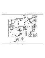
Page 69: ...63 03 12 Circuit Boards...
Page 70: ...Circuit Boards IPE2500A and IPE2500A MLS Paging Encoder Desktop Controller 64...
Page 71: ...IPE2500A and IPE2500A MLS Paging Encoder Desktop Controller Circuit Boards 65...
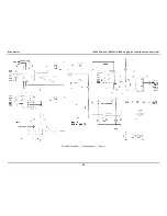
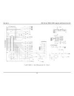
Page 73: ...67 03 12 Schematics...
Page 80: ...Schematics IPE2500A and IPE2500A MLS Paging Encoder Desktop Controller 74 Schematic Sheet 7...
Page 86: ...Schematics IPE2500A and IPE2500A MLS Paging Encoder Desktop Controller 80...


