26
44444
INST
INST
INST
INST
INSTALLA
ALLA
ALLA
ALLA
ALLATION 4
TION 4
TION 4
TION 4
TION 4
4-5
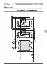
System Pressure
Fig. 4-5a Pressure Diagram
Notes on Pressures:-
1.
The additional pressure reducing valve should be fitted to the incoming main.
2.
To maintain maximum mains pressure to the kitchen tap and outside tap the
additional pressure reducing valve can be fitted following these draw offs, when
applicable.
3.
Both the pressure reducing valves MUST be set at the same pressure.
4.
The Combination Valve has an integral pressure reducing valve fixed at 3.5 bar
therefore the Hot System Pressure will be 3.5 bar maximum.
5.
If the Mains Pressure is less than 3.5 bar then the pressure in the Hot and Cold
systems will be at maximum Mains Pressure.
6.
The accumulator charge pressure is factory set at 2 Bar.
7.
The recommended accumulator charge pressure is 1.5 Bar below the mains
pressure with an absolute minimum of 0.5/0.8 Bar - consult GAH Heating Products
for further information. Also refer to 5-1.1.
8.
The Combination Valve has a Pressure Relief Valve (PRV) set at 6 Bar.
8.
The unvented cylinder has a Temperature and Pressure Relief Valve (PRV) set at 6
Bar.
ACCUMULATOR
CHARGE PRESSURE
DRAIN
BOILER
FLOW
BOILER
RETURN
HTPV
DRAIN
ACCUMULATOR
UNVENTED
CYLINDER
BALANCED
COLD SUPPLY
TO TAPS
INCOMING
MAINS
SUPPLY
HEATING
SYSTEM
FILL
SINGLE
CHECK
VALVE
COLD SYSTEM
PRESSURE
HOT WATER
SUPPLY TO TAPS
HOT SYSTEM
PRESSURE
SUPPLY
PRESSURE
MAINS
PRESSURE
PRV -6 Bar
COMBINATION VALVE
PRESSURE REDUCING
VALVE (set at 3.5 Bar)
Restricts hot system
pressure
PRESSURE REDUCING
VALVE
(set at 3.5 Bar)
Restricts cold system and
supply pressure
BOTH PRESSURE
REDUCING VALVES
MUST BE SET AT THE
SAME PRESSURE
INTEGRAL NON
RETURN VALVE
HOT SYSTEM
PRESSURE

