


10
REV 4/22
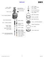
GB752SR
-
8 INSTALLATION TOOL
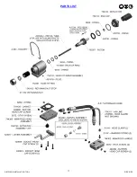
TORQUE SPECIFICATIONS
Socket Head Cap Screws (400061 and 400066) = 40 inch lbs. (4.52 Nm).
Button Head Cap Screws (A
-
928) = 40 inch lbs. (4.52 Nm).
Packing Plug (744118) = 45 foot lbs. (61 Nm).
Flexlock Nut (400559) = 40 inch lbs. (4.52 Nm).
End Cap (752313) = 45 foot lbs. (61 Nm).
Button Head Cap Screws (402482) = 35
-
40 inch lbs. (3.95
-
4.52 Nm)
(Do NOT over
-
tighten).
Note:
•
Dispose of hydraulic oil in accordance with manufacture safety datasheet.
•
All tool materials are recyclable except rubber o
’
rings, seals and wipers.
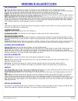
The performance of any tool depends upon good maintenance practices. Following these minimal requirements for service and care
will extend the life of your tool.
*Only use a clean dry air supply set at 90
-
100 p.s.i. (6.2
-
6.9 bar) Max. equipped with a filter
-
regulator to prevent wear.
*Proper care by operator is necessary in maintaining full productivity and reducing downtime. Read all applicable tool manuals and
nose assembly data sheets prior to operating tools.
*Keep nose assemblies, especially jaws, clean and free of chips and debris. Lube jaws and collet surfaces that jaws ride on with light
machine oil on a daily basis.
*All Screwed End Caps, Base Covers, Air Fittings, Air Actuators, Screws and Nose Assemblies are to be examined at the end of each
working shift to check that they are secure.
*Check tool, all hoses and all couplings daily for damage or air/hydraulic leaks. Tighten or replace (if necessary).
*For a complete overhaul, service tool kit (GB740SHTK) is recommended (see overhaul pg. 14
-
16).
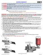
WEEKLY MAINTENANCE
•
Keep the hydraulic system full (only use Dexron® III or equivalent) and free of air by using the air bleeder assembly (704153) on a weekly
basis or as needed. (See Filling and Bleeding procedures pgs. 11
-
12).
DAILY MAINTENANCE
WARNING
:
Tool must be maintained in a safe working condition at all times and examined on a daily basis for damage or
wear. Any repair must be done by qualified personnel trained on Gage Bilt procedures.
WARNING
:
Excessive contact with hydraulic oil and lubricants must be avoided.
WARNING:
Maintenance personnel
MUST
read and understand all warnings and cautions.
WARNING
:
Disconnect tool from its power source before performing maintenance, cleaning or when replacing worn or
damaged components. Severe personal injury may occur if power source is not disconnected.
WARNING:
Read material Safety Data Sheet documents for all applicable materials.
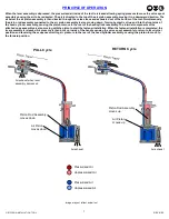
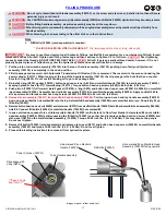
HYDRAULIC THREAD PREPARATION
IMPORTANT:
Be sure to use thread sealant on all hydraulic fittings, Loctite® 545 or equivalent or a non
-
hardening Teflon®
thread compound such as Slic
-
tite®. Tighten until fitting feels snug and then continue to tighten 1/2 to 1 full turn.
CAUTION:
Over
tightening can easily distort the threads. DO NOT USE TEFLON® TAPE.
CAUTION:
Teflon® tape is an excellent thread sealer, however,
if it is not properly applied, pieces of Teflon® may enter the hydraulic system and cause malfunction or damage.
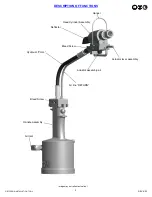
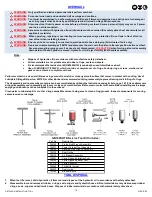
Image may not
reflect actual tool
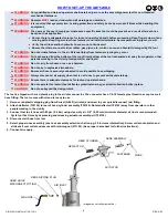
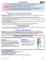
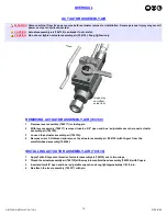
CLEANING AND LUBRICATING PROCEDURE
LUBRICATING
Lubricate nose assembly after each cleaning
and as often as needed.
1.
Disconnect tool vacuum line (if equipped).
2. Point nose assembly into oil as shown.
3. Cycle tool 8
-
10 times and wipe dry.
Daily cleaning and lubrication of nose assembly will greatly reduce downtime and increase life of components. Using sewing machine
oil, or an equivalent cleaner/lubricant, follow instructions below.
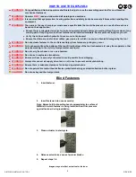
CLEANING
Clean nose assembly daily or as often as needed.
1.
Dip into mineral spirits or similar solvent to clean jaws
and wash away metal chips and debris. DO NOT allow
jaws to come in contact with other solvents. DO NOT let
jaws soak. Dry jaws immediately.
2. Disassemble nose assembly and use a sharp
“
pick
”
to remove embedded particles from grooves of jaws.