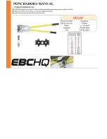
background image

16


REV 4/22


GB752SR

-

8 INSTALLATION TOOL


WARNING

Disconnect tool from its air source before disassembly.
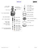
 

OVERHAUL


1.


Remove nose assembly and adapter from tool before attempting disassembly of head cylinder assembly (752124).


2.


Remove end cap (752313).


3.


Push against threaded end of piston (752507) to slide it out of head cylinder assembly (752124). Be careful not to damage 

threads or cause burrs on polished piston (752507) surface. 


The re

-

assembly sequence is the opposite of disassembly. (See Filling and Bleeding procedures pgs. 11

-

12). Apply Loctite® #242 

and torque the socket head cap screws (400061 and 400066) uniformly to 40 inch lbs. (4.52 Nm) to prevent leakage around the gasket 

(704129).


HEAD


HANDLE


To inspect air cylinder bore, remove base cover (744124). Any further disassembly will require removal of the manifold

-

handle (744303) first. 


For complete disassembly.


1.


Remove base cover (744124).


2.


Holding tool upright, remove four screws (A

-

928) and lift manifold

-

handle (744303) from handle assembly (744129) and set aside o'ring 

(S832) and gasket (704129).


3.


Empty all hydraulic oil into an approved container and dispose of in accordance with the material safety data sheet.
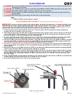


4.


Place piston rod wrench assembly (704149) down into top of power cylinder (743131) and into the hex of piston rod assembly (744136). 


While holding the piston rod wrench assembly (704149), remove flexlock nut (400559) using a 7/16" socket wrench or an adjustable 


wrench. Still holding piston rod wrench assembly (704149), remove air piston assembly (744121) using packing plug wrench assembly 


(704150), by turning counterclockwise.


5.


When air piston assembly (744121) is completely free from piston rod assembly (744136), tap or push on the piston rod wrench assembly 


(704149) to eject air piston assembly (744121) from bottom of handle assembly (744129).


6.


After removal of air piston assembly (744121), slide piston rod assembly (744136) back up to the end of its travel. Using packing plug 


wrench assembly (704150) remove packing plug (744118).


7.


With packing plug (744118) removed, power cylinder (743131) can be removed by pushing on power cylinder tool assembly (704151) 


when inserted into top of power cylinder (743131).


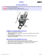
To reassemble the handle assembly (744129).


1.


Reverse the above procedure, being certain that all o'rings are properly lubricated before installation. Torque packing plug (744118) 

to 45 foot lbs. (61 Nm).


2.


Attach the seal guide (704152) to the piston rod assembly (744136) and tap the piston rod assembly (744136) through the packing 

plug (744118).


3.


Attach air piston assembly (744121) and flexlock nut (400559). Torque flexlock nut to 40 inch lbs. (4.52 Nm).


4.


Attach air piston assembly (744121) to piston rod assembly (744136).


5.


With the piston rod assembly (744136) in the down position, fill oil passage on top of handle assembly (744129) with automatic 

transmission oil, Dexron® III or equivalent. When looking at top of handle assembly (744129) the oil passage is the hole that has 

a counterbore for (S832) o'ring.


6.


Replace gasket (704129) and o'ring (S832), just prior to replacing manifold

-

handle (744303). Torque all screws to manual specifications. 

(See Filling & Bleeding procedures pgs. 11

-

12) and (See torque specs. pg. 10).
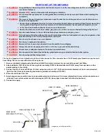
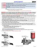
 

AIR VALVE


1.


Remove pin (744149) and muffler (744143).


2.


Insert valve extractor (S1178) into end of valve plug (744142) and pull it out.


3.


Using the same procedure, pull out valve spool assembly (743142).


4.


It should never be necessary to remove valve sleeve (743144) unless the ports in the valve sleeve (743144) are plugged from contaminated 


air. If ports are plugged, use needle nose pliers to grasp end of spring (744144), turning clockwise and pulling to dislodge from 


groove in casting. Valve spring installation tool assembly (744251) will facilitate the proper installation of the spring (744144).


5.


Valve sleeve (743144) can be pulled out using valve sleeve removal tool (744152).


Summary of Contents for GB752SR-8

Page 1: ...E BILT TOOLS ARE AVAILABLE WORLDWIDE E MAIL US FOR A DISTRIBUTOR NEAR YOU INSTALLATION TOOL 44766 Centre Court Clinton Twp MI 48038 USA Ph 1 586 226 1500 Fax 1 586 226 1505 solutions gagebilt com www...

Page 2: ...l Specifications 4 Description of Functions 5 Warnings 6 Principle of Operation 7 How to set up the GB752SR 8 8 How to use the GB752SR 8 9 Maintenance 10 Filling 11 Bleeding 12 Troubleshooting 13 Over...

Page 3: ...equent user in repairing or replacing defective goods or if the goods covered by this warranty are reworked or subjected to any type of additional processing This warranty is void if Seller is not not...

Page 4: ...setting stroke and a rated pull load of 3 800 lbs 16 9 kN with 90 psi 6 2 bar air pressure at the air inlet The GB752SR 8 split handle installation tool operates on 90 to 100 psi 6 2 6 9 bar of air p...

Page 5: ...N TOOL DESCRIPTION OF FUNCTIONS Image may not reflect actual tool Actuator lever assembly Handle Assembly Head Cylinder Assembly Deflector Air Inlet Hydraulic PULL Air line RETURN Hanger Actuator asse...

Page 6: ...ight it is recommended safety shoes be worn during operation 11 It is recommended tool be operated not more than 50 out of every 60 minutes where prolonged use is expected REPETITIVE MOTIONS HAZARDS 1...

Page 7: ...embly causing the piston to move to the rear of the head cylinder assembly The internal components of the attached nose assembly are also moving with the piston to start the fastener installation When...

Page 8: ...asteners WARNING Operator MUST read and understand all warnings and cautions WARNING It is required that eye protection hearing protection and safety boots be worn at all times while handling this equ...

Page 9: ...there is adequate clearance for tool and operator s hands before proceeding Keep fingers clear of any moving parts Keep fingers clear from fasteners and installed materials Severe personal injury may...

Page 10: ...must be maintained in a safe working condition at all times and examined on a daily basis for damage or wear Any repair must be done by qualified personnel trained on Gage Bilt procedures WARNING Exc...

Page 11: ...g hydraulic hose A 317 towards plug 704313 Torque button head cap screws A 928 to 40 inch lbs 4 52 Nm 4 Push piston 752507 full forward Install gasket 704129 o ring S832 and button head cap screws 400...

Page 12: ...t air supply Cycle tool ten times removing any air bubbles 7 Disconnect air supply Remove air bleeder assembly 704153 sold separately and replace button head cap screw 402482 and stat o seal S572 on m...

Page 13: ...be 028 71 mm Clear and size or replace 3 NO OPERATION WHEN LEVER ASSEMBLY 724017 IS DEPRESSED a Tool seized due to mechanical failure or damaged parts 4 OIL LEAKAGE a DO NOT OPERATE WITH OIL LEAKING F...

Page 14: ...bly to prevent tearing or distorting of o rings The disassembly and re assembly procedure can be accomplished by utilizing the instructions and parts list on pgs 14 18 Use extreme care during disassem...

Page 15: ...onto threads of actuator assembly air 704130 one to two wraps 2 Thread the actuator assembly air 704130 all the wayinto manifold head assembly 744306 with fingers 3 Insert and turn 5 8 open end box a...

Page 16: ...emoval of air piston assembly 744121 slide piston rod assembly 744136 back up to the end of its travel Using packing plug wrench assembly 704150 remove packing plug 744118 7 With packing plug 744118 r...

Page 17: ...17 REV 4 22 GB752SR 8 INSTALLATION TOOL PARTS LIST...

Page 18: ...18 REV 4 22 GB752SR 8 INSTALLATION TOOL PARTS LIST...

Page 19: ...is material undergoes combustion ACCIDENTAL RELEASE MEASURES Protective Measures Eliminate all sources of ignition in vicinity of spilled material Spill Management Stop the source of the release if yo...

Page 20: ...43OS 5 32 5CEA 751 23 5CEA 352 61 45CEA 751B 54RA 5CEA 751 43OS 3 16 6CEA 751 23 6CEA 352 61 6CEA 751C 54RA 6CEA 751 43OS 3 32 3N 751 23 3N 352 61 3N 751B 54RA 3N 751A 43OS 1 8 4CES 751 23 4CES 352 61...

Page 21: ...Adapter Assembly 730715 Adapts GB715 Series Nose Assemblies to GageBiltGB752 GB730 GB713 GB731 GB722 Sold Separately Adapter Assembly 751204 Adapts 204 offset series nose assemblies to GB752 installat...

Page 22: ...kg Entire tool weight 4 75 lbs 2 2 kg Pull load 3 800 lbs 16 9 kN 5ftHyd HosesarerecommendedwithuseofBackpack Additional custom lengths are available GB752SH Stroke 500 12 7 mm Hand held weight 2 50 l...

Page 23: ...23 REV 4 22 GB752SR 8 INSTALLATION TOOL This page intentionally left blank...

Page 24: ...A REGISTERED TRADEMARK OF FISKE BROTHERS REFINING CO CHERRYMAX AND CHERRYLOCK ARE REGISTERED TRADEMARKS OF CHERRY AEROSPACE FASTENERS SLIC TITE IS A REGISTERED TRADEMARK LA CO INDUSTRIES Riveter Kits...

Reviews: