background image

2

Governors America Corp. © 2021 Copyright All Rights Reserved

ESD5500-II Fusion Series Speed Control Unit  1-2020-A4    PIB2180 

3

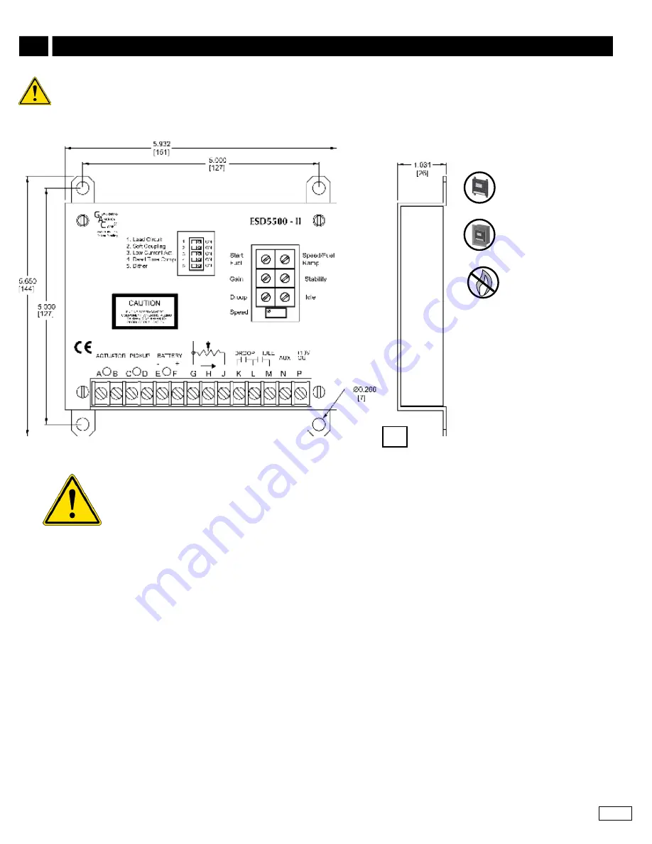
INSTALLATION

Mount in a cabinet, en-

gine enclosure, or sealed 

metal box.

Preferred vertical orienta-

tion allows for the draining 

of fluids in moist environ

-

ments.

Avoid Extreme Heat

Dimensions:  

in

 [mm]

• 

An overspeed shutdown device, independent of the governor system, should be used to prevent loss of 

engine control which may cause personal injury or equipment damage.

• 

Do not rely exclusively on the governor system electric actuator to prevent overspeed. A secondary shutoff 

device, such as a fuel solenoid must be used.

When wiring eSD5500-II Series controllers:
1.  Use shielded cable for all external connections to the eSD controller

.

2.  One end of each shield, including the speed sensor shield, should be grounded to a single point on the ESD case.
3.  Terminal A, B, E,and F should be 16 AWG or larger. Long cables require increased wire size to minimize voltage drops. 
4.  Magnetic speed sensors Terminals C and D must be twisted and or shielded for the entire length. 
5.  The gap between the speed sensor and the ring gear teeth should be smaller than 0.02 in [0.5 mm] usually backing out 3/4 turn after 

touching ring gear teeth. Speed sensor voltage should be at lease 1 V AC RMS during cranking. 

6.  Terminal P is used to 10 V DC regulated supply to accessories. No more than 20 mA of current can be drawn from this supply. 

Ground reference is Terminal G. A short circuit in this terminal can damage the speed control unit.

7.  Do not over-tighten terminals

. Torque to no greater than 9.0 in-lb ±2.5 [1.01 ±0.28 N∙m].

reaD THIS enTIre GUIDe Before PerformInG an InSTaLLaTIon. 

Summary of Contents for Fusion Series

Page 1: ...Speed Signal Range 1 0 50 0 V AC Actuator Current 77 F 25 C 8 A MAX Continuous Speed Sensor Signal 1 0 120 V RMS Environmental Ambient Temperature 40 to 85 C 40 to 180 F Relative Humidity up to 95 All...

Page 2: ...SD controller 2 One end of each shield including the speed sensor shield should be grounded to a single point on the ESD case 3 Terminal A B E and F should be 16 AWG or larger Long cables require incr...

Page 3: ...2 Use shielded cable for all external connections to the ESD controller One end of each shield including the speed sensor shield should be grounded to a single point on the ESD case A 15 amp fuse mus...

Page 4: ...ol When the engine is at idle speed the speed control unit applies droop to the speed controller to ensure stable operation Gain Middle Position 50 Stability Middle Position 50 Speed Middle Position 5...

Page 5: ...procedure steps 1 3 as the Gain parameter Gain Stability Start Fuel Speed Fuel Ramp Start the engine and accelerate directly to the operating speed METHOD 1 Procedure 1 Remove the connection between T...

Page 6: ...an damage the speed control unit Never jumper Terminal P directly to Terminal N Droop is typically used for paralleling engine driven generators When in droop operation the engine speed will decrease...

Page 7: ...ce Defective speed sensor 3 P G 10 V DC Internal Supply Short on Terminal P Defective speed control unit 4 F A 1 0 2 0 V DC while cranking Speed parameter set too low Short open in actuator wiring Def...

Page 8: ...stem or b 14 V for a 24 V DC system Then Check or replace battery Momentarily connect Terminals A and F The actuator should move to the full fuel position Actuator or battery wiring in error Actuator...

Reviews: