background image

40 


4.2.3


Communication 

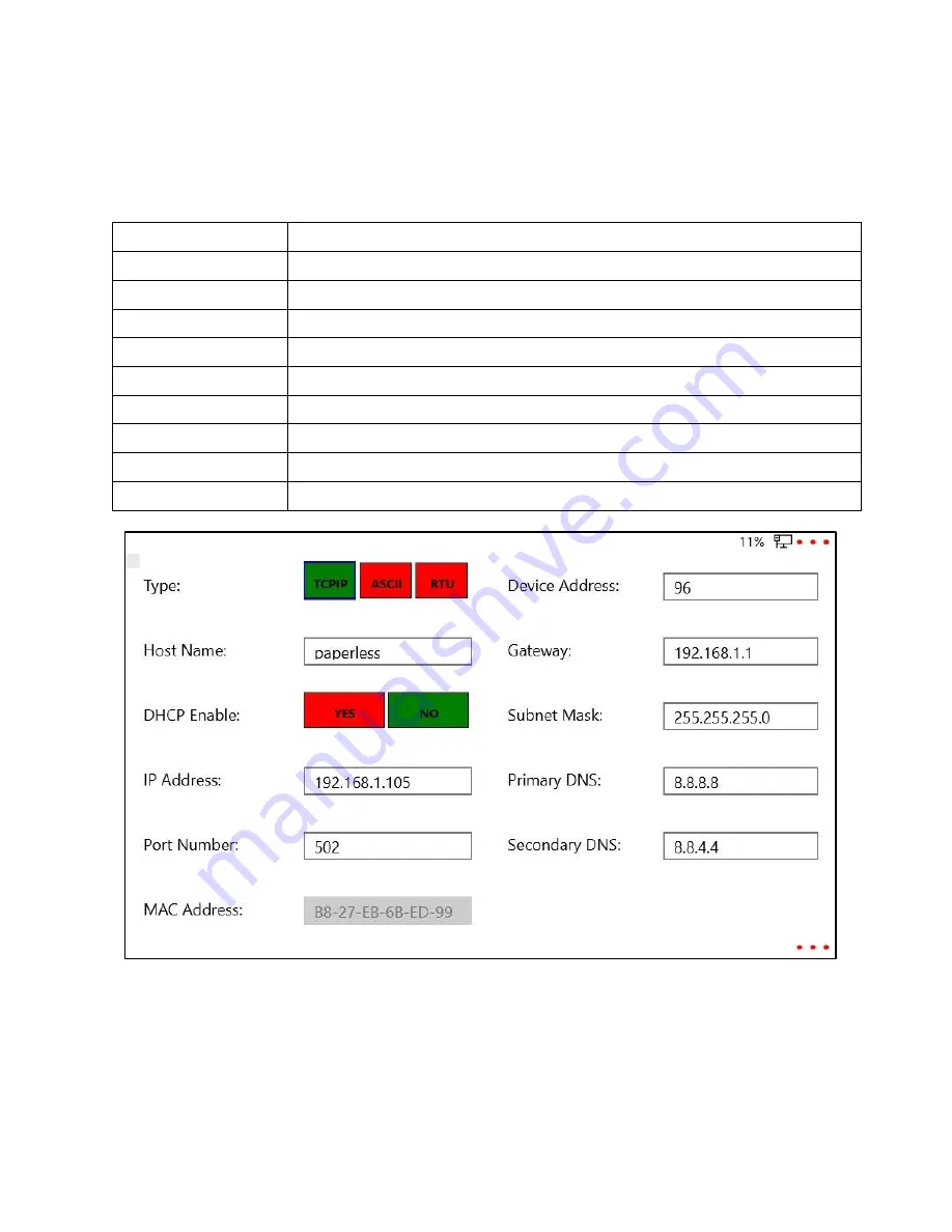
Press on the text block to modify the following network and communication parameters: 


Table 5 Communication Parameters


Host Name 

Name of Host - Maximum 15 characters (Required) 

MAC Address 

MAC Address of Device (Required) 

DHCP Enable 

Yes 

 to enable and No 

 to disable 

IP Address 

Enter valid IP Address of Device (e.g. 192.168.0.34) (required) 

Port Number 

Port Number (Numeric value only) (Required) 

Device Address 

Enter a valid Device Address (Required) 

Gateway 

Enter a valid Gateway (should not be null) (Required) 

Subnet Mask 

Enter a valid Subnet Mask (should not be null) (Required) 

Primary DNS 

Enter a valid Primary DNS (should not be null) (Required) 

Secondary DNS 

Enter a valid Secondary DNS (should not be null) (Required) 


      Figure 47 -Network Parameters


Summary of Contents for 62 Series

Page 1: ...Paperless Recorder Model No 62xx G Tek Corporation Pvt Ltd 3 mahavir estate karelibaug vadodara 390 018 tel 91 265 2461912 email info gtek india com url www gtek india com OPERATING MANUAL...

Page 2: ...nfiguration 23 4 1 5 Group 25 4 1 6 Create Batch 28 4 2 SYSTEM SETUP 31 4 2 1 Locale 31 4 2 2 Back Restore 33 4 2 3 Communication 40 4 2 4 Factory Setting 42 4 2 5 Screen Setup 53 4 2 6 Clear Memory 5...

Page 3: ...re 23 Modifying Group 26 Figure 24 Mandatory fields blank error 27 Figure 25 Invalid field value entered error 27 Figure 26 Group Information Updated Successfully 27 Figure 27 Manual Batch config 28 F...

Page 4: ...tion successful for mAmp 52 Figure 73 Clear Memory 53 Figure 74 Wrong password error message 54 Figure 75 Confirmation message for clear memory 54 Figure 76 Final confirmation for clear memory 54 Figu...

Page 5: ...iguration parameters 19 Table 2 Additional Channel Configuration parameters 20 Table 3 Modify Group parameters 26 Table 4 Create Batch parameters 28 Table 5 Communication Parameters 40 Table 6 Chart S...

Page 6: ...This section enlists all the tables and figures for user s reference Section 2 Introduction This section gives an outline of the manual a brief description about the paperless recorder and its dimens...

Page 7: ...6 3 2 INSTALLATION Figure 1 Overall Dimensions Height and Width Figure 2 Overall Dimension Depth...

Page 8: ...7 Figure 3 Panel Mounting...

Page 9: ...ts and outputs conform to Mains Power Input Insulation Category ll All connections to secondary circuits must have basic insulation After installation there must be no access to live parts e g termina...

Page 10: ...problem can be eliminated using suitable suppression devices across the coil Coil transients can also be transmitted through the air so the recorder itself should be mounted as far as possible from p...

Page 11: ...e which is apparently bigger in diameter is the Earthing line Now take the voltmeter with appropriate measurement range normally 750VAC or higher and put the probes into PHASE and NEUTRAL line and tak...

Page 12: ...wiring As shown in the following figure Figure 4 Back Panel of Paperless Recorder The Paperless Recorder can be connected and configured to operate with a variety of signal sources as thermocouple RTD...

Page 13: ...n All signal wiring should use ground shielded wires or be routed through grounded conduit This minimizes the effects of RFI and ESD 3 Care should be taken when wiring to relay or solenoid coils as la...

Page 14: ...color Connect two similar color wires at and G pin Connect the remaining dissimilar color wire at Similarly connect for all other channels Notes 1 When wiring RTDs lead length and diameter must be ch...

Page 15: ...6 Sensor Wiring Thermocouple mV Input Connect the 2 wires of sensor at of sensor connector as shown in Figure 7 3 3 1 1 2 Sensor wiring 4 20mA 0 20mA Input Connect the wire at pin 1 and wire at pin 2...

Page 16: ...1 is externally supplied If you want to connect more than one instrument in series than recorder should be placed in such a way that not more than 250 of load resistance is added in the loop after re...

Page 17: ...ith Transmitter and External Power Supply Connection of Paperless Recorder with Transmitter and External Power Supply is as shown in Figure 9 The shunt of 50 is externally supplied 3 3 1 1 4 Sensor wi...

Page 18: ...using TCPIP Interface through GtekNet software developed by G Tek For this RJ 45 connector is given on the back panel of the Paperless Recorder A Crossover TCPIP Cable is required to connect Paperles...

Page 19: ...lowing options will be available Press any one of these options to view or set them Main menu page header displays path of the current selection For instance Figure 11 Menu Page Header Here to configu...

Page 20: ...7f Multiplier Channel Multiplier value minimum 3276 8f and maximum 3276 7f Range Low Channel Range Low value minimum 3276 8f and maximum 3276 7f Span Channel Span value minimum 3276 8f and maximum 327...

Page 21: ...ion parameters Channel Number Auto generated fixed number of channels Channel Tag User defined tag of channel required field Channel color Color of channel tab and line Select a channel color from the...

Page 22: ...ton Update And Previous which will update channel configuration to device and opens previous channel Configuration page Error messages If mandatory fields are left blank error will be generated as bel...

Page 23: ...tings Figure 17 Confirmation message for channel configuration Following message is displayed when channel configuration is updated successfully Figure 18 Channel Configuration Updated message 4 1 3 O...

Page 24: ...nfiguration A relay configuration provides 4 relays Figure 19 Relay Configuration Each single relay can be configured for multiple channels There are three type of relay configuration is available Fig...

Page 25: ...ue Table Click on Update and Next for next relay configuration or click on Update and previous for previous relay configuration or click on Update and Exit to save the configuration for selected relay...

Page 26: ...be added or deleted but can only be modified while batch is not running Group is useful while configuring a new Preconfigured batch By selecting group in a batch the channels within that group will be...

Page 27: ...0 characters Channels Select channels Orange color shows selected channel On clicking button Update and Exit group information is updated and exit from the group menu Figure 23 Modifying Group On clic...

Page 28: ...4 Mandatory fields blank error If incorrect values are entered error messages for invalid fields are displayed Figure 25 Invalid field value entered error Following message is displayed when group inf...

Page 29: ...interval Store Interval maximum number of readings in trend No of readings in Trend Number of readings in trend minimum 2 and maximum 500 Batch Type Select batch type Manual or Preconfigured Start Dat...

Page 30: ...ill start and stop every interval mentioned in Start and Stop time Figure 28 Preconfigured batch Fill the appropriate information in the relevant field to add new batch Notes If batch is running when...

Page 31: ...re left blank an error message will be generated Figure 29 Create Batch Error message for blank fields If incorrect values are entered error messages for invalid fields are displayed Figure 30 Create...

Page 32: ...tory calibration 4 Perform channel calibration 5 Modify communication parameters 6 Set display brightness 7 Upgrade software 4 2 1 Locale Paperless Recorder can be used in 6 different languages Englis...

Page 33: ...following message is displayed Figure 32 System language successfully changed to French On clicking button Select RTC RTC Real Time Clock i e time date and time zone of the device can be changed On c...

Page 34: ...33 4 2 2 Back Restore User can take archive file backup of historical data of batch to USB with file extension arc Path Menu System Setup Backup Restore Figure 34 Backup Restore menu options...

Page 35: ...h start and batch stop time Figure 35 Batch details displayed on Backup Restore page On pressing button Export user can export historical batch data in archive format to USB device In case USB device...

Page 36: ...ogs regarding paperless activities will export to USB pen drive Once all the logs will be exported to pen drive the message will appear as follows Figure 37 Log downloaded successfully If Pen drive is...

Page 37: ...ress Configuration Backup the set configuration will be exported to the USB pen drive in the form of folder named as Configuration File Once the backup is exported successfully then below message will...

Page 38: ...ach USB Pen drive where the Configuration File is available and press the Configuration Restore on the paperless device First the message appears asking for the confirmation as follow Figure 41 Config...

Page 39: ...Database Backup Whole database will be exported to the USB pen drive in the form of folder named as Database Backup Once database is exported to the USB pen drive successfully then message appears as...

Page 40: ...he database attach the USB pen drive where Database Backup folder is available Press Database Restore on the paperless device the following message will appear Figure 45 Database Restore If the USB pe...

Page 41: ...disable IP Address Enter valid IP Address of Device e g 192 168 0 34 required Port Number Port Number Numeric value only Required Device Address Enter a valid Device Address Required Gateway Enter a...

Page 42: ...nication configuration error for blank fields If incorrect values are entered error messages for invalid fields are displayed Figure 49 Communication Configuration error for invalid field values enter...

Page 43: ...on Parameters updated successfully 4 2 4 Factory Setting From this menu user can calibrate channel touch restore device restore configuration and update software Path Menu System Setup Factory Setting...

Page 44: ...1 of the connector Similarly connect the first white wire of RTD in pin 2 Connect the second white wire in pin 3 as shown in figure W W R Figure 52 Connection for 3 wire RTD calibration For 4 wire RT...

Page 45: ...r RTD for respected card select 1st channel of that card as calibrate channel click on RTD and apply input as per shown in the message below and click on next button Figure 54 RTD Calibration 20 ohm F...

Page 46: ...45 If an invalid value is applied then the error message will appear as follow Figure 56 Calibration error message for RTD Figure 57 Calibration successful for RTD...

Page 47: ...connector as shown in below figure Figure 58 Connection for mVolt Calibration To perform the calibration for thermocouple for respected card select 1st channel of that card as calibrate channel click...

Page 48: ...47 Figure 60 Thermocouple 80 mV If invalid input value is applied then following error message will appear Figure 61 Calibration error message for mVolt...

Page 49: ...age will appear Figure 62 Calibration Successful for mVolt 4 2 4 1 3 Volt Calibration Connect positive ve terminal in 1st pin of the connector and negative ve terminal in 2nd pin of the connector Figu...

Page 50: ...libration for Voltage for respected card select 1st channel of that card as calibrate channel click on Volt and apply input as per shown in the message below and click on next button Figure 64 Volt 5...

Page 51: ...for volt calibration On successful calibration following message will appear Figure 67 Calibration successful for Volt 4 2 4 1 4 mA Calibration Connect positive ve terminal in 1st pin of the connecto...

Page 52: ...alibration for mAmp for respected card select 1st channel of that card as calibrate channel click on mA and apply input as per shown in the message below and click on next button Figure 69 mA 0 Volt F...

Page 53: ...lid input value is applied then following error message will appear Figure 71 Error message for mAmp calibration On successful calibration following message will appear Figure 72 Calibration successfu...

Page 54: ...4 2 4 5 Software Upgrade Note Current software version does not contain this feature It will be available in future version 4 2 5 Screen Setup Note Current software version does not contain this feat...

Page 55: ...age will appear for confirmation Figure 75 Confirmation message for clear memory On pressing Yes again another message will appear for final confirmation as follow Figure 76 Final confirmation for cle...

Page 56: ...batch data for selected history batch 4 3 1 Event Summary Note Current software version does not contain this feature It will be available in future version 4 3 2 Historical Data Batch List User can...

Page 57: ...ntainer folder On pressing button View horizontal line graph of selected historical batch can beviewed On pressing button historical data from View page it opens a list of historical batches Here user...

Page 58: ...gure 79 Historical Data between a time interval On pressing View batch data can be viewed as a Horizontal trend graph a vertical trend graph or a polar graph Historical Graph Historical Graph shows th...

Page 59: ...58 Figure 81 Historical Vertical Graph Figure 82 Historical Polar Graph...

Page 60: ...On clicking button Previous it displays the graph of previous cycle of selected chart speed for selected batch 3 Next On clicking button next it displays the graph of next cycle of selected chart spee...

Page 61: ...istorical graph User can see the graph for specific channels by skipping the unwanted channel on the legend shown on left side User should only click on the channels shown on the left side in the lege...

Page 62: ...61 Figure 86 Skip channel in the historical graph User can insert the mark on the graph for specific time on the graph by clicking on Marker On button Figure 87 Graph marker...

Page 63: ...62 User can insert a note at specific time for any important event by clicking on the channel when marker is on Figure 88 Insert operator note...

Page 64: ...Start button Note If SD card memory is less than 500 MB and if current batch is Stopped user is not allowed to click on Start button because it is not enabled Current data can be viewed in the form o...

Page 65: ...Figure 90 Group menu on current data page On clicking Channels a sliding window which contains all channels within a group is opened User can enable disable any of the channels from this sliding wind...

Page 66: ...65 Figure 91 Channel selection menu on current data page By default all current data pages show last selected group and channels...

Page 67: ...r of each channel data Digital View page updates after every 5 second By default it shows first group and its channels User can select group and channel from bottom panel Digital View shows only those...

Page 68: ...panel and select channels Horizontal Bar Graph page shows only those channels which are selected Figure 93 Horizontal Bar Graph for current data Horizontal Bar Graph shows current Data vs channels Cha...

Page 69: ...l also selects channels Vertical Bar Graph page shows only those channels which are selected Figure 94 Vertical Bar Graph view for current data Vertical Bar Graph shows channels Vs current data Channe...

Page 70: ...l selected for current batch User can select group as well as channels from bottom panel Online Trend Graph page shows only those channels which are selected Line Graphs and Circular Polar charts are...

Page 71: ...scaling facility as per minimum and maximum current data for all series Table 6 Chart Speed Selected V S Graph Update Rate Chart Speed Selected Graph Update Rate 5 minutes 5 Seconds 10 minutes 10 Sec...

Page 72: ...h page updates after every trend interval selected for current batch User can select groups as well as channels from left side panel Online Strip Graph page shows only those channels which are selecte...

Page 73: ...representation Data vs Time of the data with the radial axis indicating data value while the angular axis representing time Chart Speed set in channel configuration is the maximum time interval repres...

Page 74: ...73 6 DEVICE TOUR This menu is not available in current version...

Page 75: ...74 7 ABOUT This menu shows the information regarding the company Figure 98 About Menu...

Page 76: ...r can see the device information such as Version no Product code Serial No Display size Analog input type No of analog input channels Power supply Transmitter power Relay Analog O P and PC interface F...

Page 77: ...76 9 HELP Help regarding the operation of the device is availble in this menu Figure 100 Help Menu...

Page 78: ...updated as per input type and range Solution a Check channel configuration parameters b Check sensor connection wiring c If the problem still persists re calibrate the channel d Try factory reset on t...

Page 79: ...from the main menu e Then select the first option and system language options will be seen 7 Problem Screen is stuck or is loading for more than 5 minutes Solution Wait for up to 10 min the device sh...

Page 80: ...ese General Specifications CPU 1 2 GHz 64 bit quad core ARMv8 CPU Internal Data Storage SD Card 16GB Expandable to 32GB USB Host 1 In Front Data Update Rate 2 Hz Data Store Interval 1 seconds to 18 Ho...

Page 81: ...o table 1 Range and Accuracy Refer to table 1 Linearization For RTD Thermocouples Square Root 3 2 Power 5 2 Power Log10 Linearization Error 0 05 C Max Resolution User Settable up to 0 0001 CJC Accurac...

Page 82: ...m Load Resistive 600 Maximum Load Inductive 50mH Max Current Output 24 mA Short Circuit Protection Yes Voltage Range 0 5V 0 10V 5V 10V DC Output Impedance 1 K Maximum Maximum Capacitive Load 1 F Max L...

Page 83: ...ature Coefficient ppm C RTD Type Pt 100 IEC751 200 to 850 0 01 C 0 04 0 04 30ppm T C Type J IEC584 1 210 to 1200 0 02 C 0 03 0 05 25ppm K IEC584 1 270 to 1372 0 04 C 0 03 0 05 25ppm C Hoskins 0 to 230...

Reviews: