background image

-6-

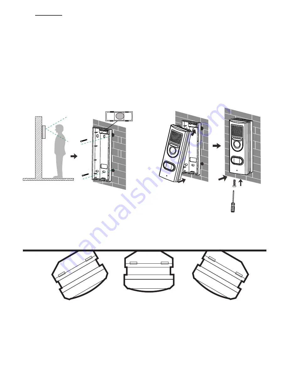
Mounting:

1. Determine the installation height for the outdoor unit.

2. Hold the suspension bracket against the wall at the desired height and draw the 

drill holes.

3. Drill the holes, insert the plugs and mount the suspension bracket. You can 

suspend the bracket exactly straight using the built-in spirit level. When using an 

external power source, lead the wires through the hole in the rear of the suspen-

sion bracket and connect them to the connection strip.

4. Now first slide the top of the outdoor unit into the suspension bracket and then 

push the bottom into the bracket, according to the illustration below.

5. Now fasten the outdoor unit into the bracket using the supplied screw.

If the camera must be aimed at an angle to the left or right, first mount the wall 

bracket at an angle to the wall and then place the straight wall bracket onto it.

Summary of Contents for FDC-250

Page 1: ...USER S MANUAL FDC 250...

Page 2: ...Time and date 11 7 4 Key tone 11 7 5 Automatic snapshot 11 7 6 To view photos 12 7 7 Reset to factory settings 12 8 EXPANDING WITH MULTIPLE OUTDOOR UNITS 13 8 1 Introduction 13 8 2 To register additio...

Page 3: ...these photos 2 INTENDED USE The Fysic FDC 250 allows you to wirelessly see who s at the door and to commu nicate with this person The Fysic FDC 250 is only suitable for household use and can in no wa...

Page 4: ...battery cover back onto the indoor unit 4 You may also place the belt clip 5 Place the indoor unit into the charger and leave it there for 10 15 hours to properly charge the battery pack The charge i...

Page 5: ...o the bottom of the outdoor unit Power adaptor 8 12V AC or DC 1000mA excluded 1 Remove the seal cover by unscrewing the 4 small screws 2 Connect the 8 12V adaptor according to the illustration below 3...

Page 6: ...external power source lead the wires through the hole in the rear of the suspen sion bracket and connect them to the connection strip 4 Now first slide the top of the outdoor unit into the suspension...

Page 7: ...ht soft button to show images to unlock 10 Switch for clicking the external antenna outward for improved range 11 External antenna 12 Built in speaker 13 Battery compartment 14 Charger 15 Adaptor cabl...

Page 8: ...matically and is stored in the memory of the indoor unit see also chapter 9 when you do nothing the call is ended automatically after 20 seconds if you want to ignore this visit press the button the i...

Page 9: ...he camera and take a picture briefly press the button to switch on the indoor unit from its sleep mode press and hold the soft button for 1 second to switch on the monitor function the display will be...

Page 10: ...briefly press the button to wake up the indoor unit 2 press the MENU soft button 3 use the and buttons to select the Volume function 4 press the Select soft button 5 use the and buttons to set the vol...

Page 11: ...to wake up the indoor unit 2 press the MENU soft button 3 use the and buttons to select the Key tone function 4 press the Select soft button 5 use the and buttons to select whether you want to switch...

Page 12: ...on Now the last photo taken will appear in the display The red letter in the upper part of the screen indicates which camera has taken the photo The green digits represent the photo number Press the D...

Page 13: ...ct the adaptor to the unit 3 Keep both the indoor unit and outdoor unit handy 4 Keep a small screwdriver or paperclip handy To register 1 with the indoor unit on stand by first briefly press the but t...

Page 14: ...y press the button to wake up the indoor unit 2 Now simultaneously press the button and the right button and press and hold these buttons for 5 seconds 3 After 5 seconds the message Registration Clear...

Page 15: ...t briefly press the button to wake up the indoor unit 2 press the Replay soft button the most recent photo will be shown 3 use the and buttons to scroll the photo directory 4 in the bottom of the scre...

Page 16: ...lay of the indoor unit 2 To talk to your visitor press the button to accept the call 3 Press the button to activate the door lock 4 Your visitor can now open the door and enter 11 3 Door lock connecti...

Page 17: ...TEM ERROR If you think that an error has occurred in the system please remove the batteries from the indoor unit and outdoor unit Now wait several minutes and replace the batteries If this does not re...

Page 18: ...s 2 1mm F2 6 Viewing Angle Diagonal 135 Minimum Illumination 1 LUX without LED illumination LED 6 LEDs Power Requirement 8 12V AC or DC 5 4 LR6 AA 1 5V alkaline batteries Power Consumption 500mA Max c...

Page 19: ...19...

Page 20: ...ef Tarif local DE 0180 503 0085 Lokale Festnetzkosten Hesdo Australi laan 1 5232 BB s Hertogenbosch The Netherlands WWW FYSIC COM SERVICE FYSIC NL NL 073 6411 355 BE 03 238 5666 DE 0180 503 0085 Hesdo...

Reviews: