


3. ADJUSTMENTS AND CHECKS
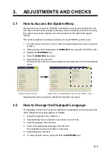
3-6
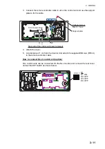
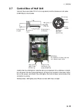
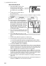
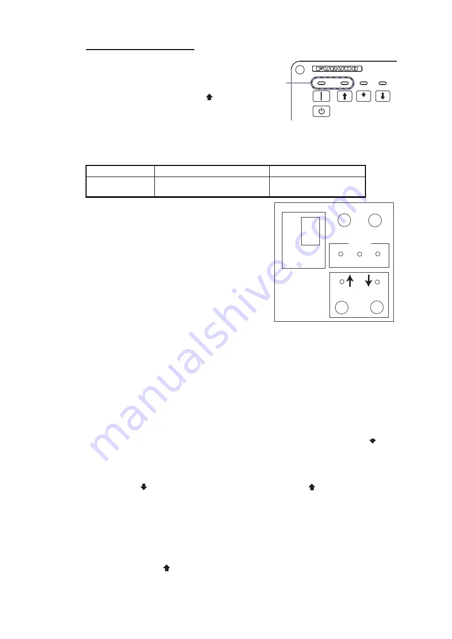
How to check the hull unit
1. Press the POWER (
│
) switch on the
control unit to turn on the system.
Check that both the “ON” LED above
the POWER switch and the are
lit.
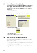
2. Confirm that the 5V and UP LEDs on
the control box are lit.
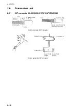
3. Remove the cover of the control box and use a multimeter to measure the follow-
ing voltages:
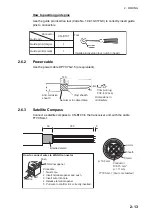
4. In the control box, set the TEST/NORMAL
switch to “TEST”. Press the DOWN switch to
confirm that the transducer lowers. Also, while
the transducer is being lowered, check that
the MD LED lights when the MD L. SW kicks.
Note that the MD L. SW does not stop the
transducer when the TEST/NORMAL switch
is in the TEST position.
5. Press and release the [DOWN] switch during
lowering. Confirm that the transducer stops
lowering.
6. Press the [DOWN] switch again to re-start
lowering. Confirm that the transducer stops at the moment the lower limit switch
kicks.
7. Confirm that the [UP] switch operates in a similar manner.
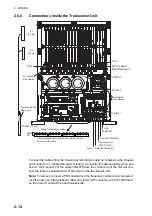
8. Check that LEDs on the panel of the control box light as follows:
1) The UP, MD and DN LEDs light when corresponding limit switch is kicked.
2) The UP and DN LEDs light while UP and DOWN switches are pressed and ex-
tinguish when the switches are released.
9. Set the TEST/NORMAL switch to “NORMAL”.
10. Check that the transducer is fully retracted. At the control unit, press the (mid-
protrusion position) switch. Confirm that the LED above the switch blinks while the
transducer is being lowered, a short beep sounds when the mid limit switch kicks,
and the LED lights when the transducer stops at the mid position.
11. Press the
switch (fully lowered position) and then the switch. Confirm that
the LED above the respective switch blinks while the transducer is being lowered
or raised, and a short beep sounds when the lower or upper limit switch is kicked,
and the LED lights when the transducer is fully lowered or raised.
12. Press the OFF switch. Confirm that the transducer is completely retracted and the
power is off.
13. With the transducer lowered (mid or fully lowered), confirm that the transducer is
raised when the switch or the OFF switch is pressed.
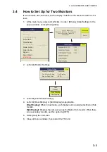
Terminal
Terminal No.
Voltage
TB-C101
(1) - (2) (2) - (3) (1) - (3)
220 VAC 220 VAC
220 VAC
Check these
LEDs are lit.
OFF
TEST
NORMAL
5V
L.SW
UP MD DN
UP DOWN
Summary of Contents for FSV-85
Page 28: ...1 HOW TO INSTALL THE SYSTEM 1 20 This page is intentionally left blank ...
Page 56: ...3 ADJUSTMENTS AND CHECKS 3 10 This page is intentionally left blank ...
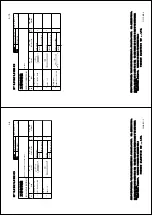
Page 67: ...12 Nov 2010 Y NISHIYAMA D 1 ...
Page 68: ...4 Feb 2011 Y NISHIYAMA D 2 ...
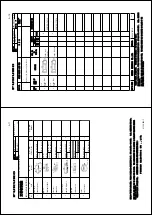
Page 69: ...5 Nov 2010 Y NISHIYAMA D 3 ...
Page 70: ...4 Apr 2014 H MAKI D 4 ...
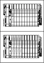
Page 71: ...6 Jul 2012 Y NISHIYAMA D 5 ...
Page 72: ...Nov 22 06 T Matsuguchi D 6 ...
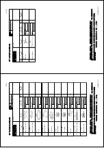
Page 73: ...22 Apr 2013 Y NISHIYAMA D 7 ...
Page 74: ...22 Apr 2013 Y NISHIYAMA D 8 ...
Page 75: ...26 Nov 2010 Y NISHIYAMA D 9 ...
Page 76: ...27 Dec 2010 Y NISHIYAMA D 10 ...
Page 77: ...Nov 22 06T Matsuguchi D 11 ...
Page 78: ...D 12 ...
Page 79: ...29 Mar 2011 Y NISHIYAMA D 13 ...
Page 80: ...13 Sep 2011 Y NISHIYAMA D 14 ...
Page 81: ...13 Sep 2011 Y NISHIYAMA D 15 ...
Page 82: ...Mar 14 07 R Esumi D 16 ...


