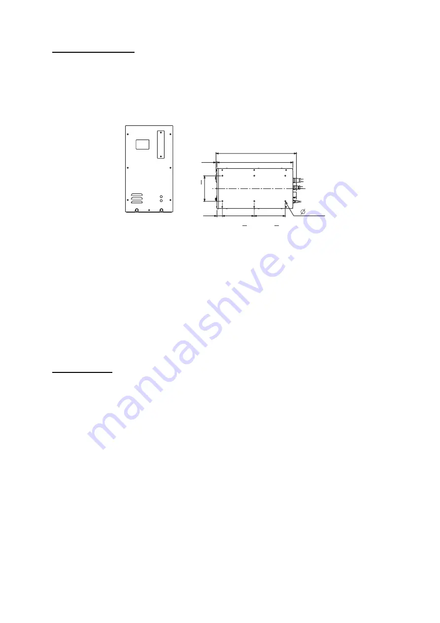
1-9
Mounting procedure
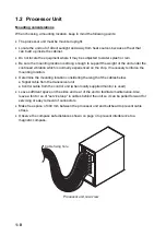
1. Unfasten two bolts from the bottom of the front side of the processor unit. Pull the unit
toward you to separate it from the mounting base.
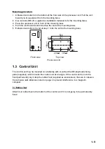
2. Use six bolts (M6
×
20, supplied as installation material) to fix the mounting base.
3. Place the processor unit in front of the mounting base.
4. Push the unit forward until it touches the end of the mounting base.
5. Refasten two bolts removed at step 1 to fix the unit to the mounting base.
504
477
5.5
160+1
34
200+1 195+1
8
Front view
Top view
Processor unit
1.3 Control Unit
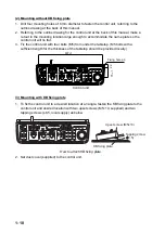
The control unit may be mounted on a tabletop with or without the KB (keyboard) fixing
plate (supplied), which mounts the control unit at an angle. If the control unit is not to be
fixed permanently, lay it atop the rubber feet (supplied as accessories). Be sure to observe
the compass safe distances noted on page ii to prevent interference to a magnetic
compass.
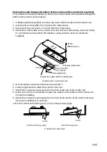
(1) Rubber feet
Attach four rubber feet to the bottom of the control unit if it is not going to be permanently
fixed.
Summary of Contents for FSV-30
Page 56: ...3 16 This page intentionally left blank ...
Page 60: ...4 4 This page intentionally left blank ...
Page 68: ...D 1 ...
Page 69: ...D 2 ...
Page 70: ...D 3 ...
Page 71: ...Y Hatai D 4 ...
Page 72: ...Y Hatai D 5 ...
Page 73: ...Takahashi T Y Hatai D 6 ...
Page 74: ...Takahashi T Y Hatai D 7 ...
Page 75: ...Y Hatai D 8 ...
Page 76: ...D 9 ...
Page 77: ...D 10 ...


