1-15
1.8 Installing the Attachment Kit (option)
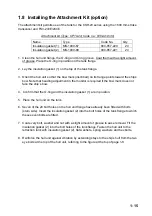
The attachment kit permits use of the tank for the CSH-20 series using the 1600 mm stroke
transducer and FSV-243E/244E.
Attachment kit (Type: OP10-24, Code no.: 006-943-530)
Name Type
Code
No.
Qty
Insulation gasket (1) MS-1000-67
000-857-220
24
Insulation gasket (2) MS-1000-68
000-857-221
24
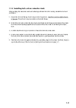
1. Clean the hull unit flange, the O-ring and O-ring groove. Coat them with a slight amount
of grease. Place the O-ring in position on the tank flange.
2. Lay the insulation gasket (1) on the top of the tank flange.
3. Orient the hull unit so that the bow mark (inscribed) on its flange points toward the ship’s
bow. Note that heading adjustment in the monitor is required if the bow mark does not
face the ship’s bow.
4. Confirm that the O-ring and the insulation gasket (1) are in position.
5. Place the hull unit on the tank.
6. Seven of the 24 bolt holes on the hull unit flange have already been fitted with bolts
(stern side). Insert the insulation gasket (2) into the bolt holes of the tank flange to which
these seven bolts are fitted.
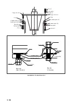
7. Coat every bolt, washer and nut with a slight amount of grease to ease removal. Fit the
insulation gasket (2) into the bolt holes of the tank flange. Fasten the hull unit to the
retraction tank with insulation gasket (2), flat washers, spring washers and hex bolts.
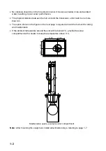
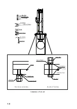
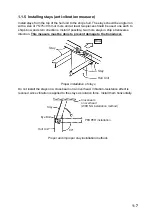
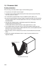
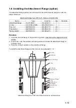
8. Reinforce the hull unit against vibration by extending stays to the ship’s hull from the two
eye bolts at the top of the hull unit, referring to the figure at the top of page 1-8.
Summary of Contents for FSV-30
Page 56: ...3 16 This page intentionally left blank ...
Page 60: ...4 4 This page intentionally left blank ...
Page 68: ...D 1 ...
Page 69: ...D 2 ...
Page 70: ...D 3 ...
Page 71: ...Y Hatai D 4 ...
Page 72: ...Y Hatai D 5 ...
Page 73: ...Takahashi T Y Hatai D 6 ...
Page 74: ...Takahashi T Y Hatai D 7 ...
Page 75: ...Y Hatai D 8 ...
Page 76: ...D 9 ...
Page 77: ...D 10 ...

