background image

 4-6

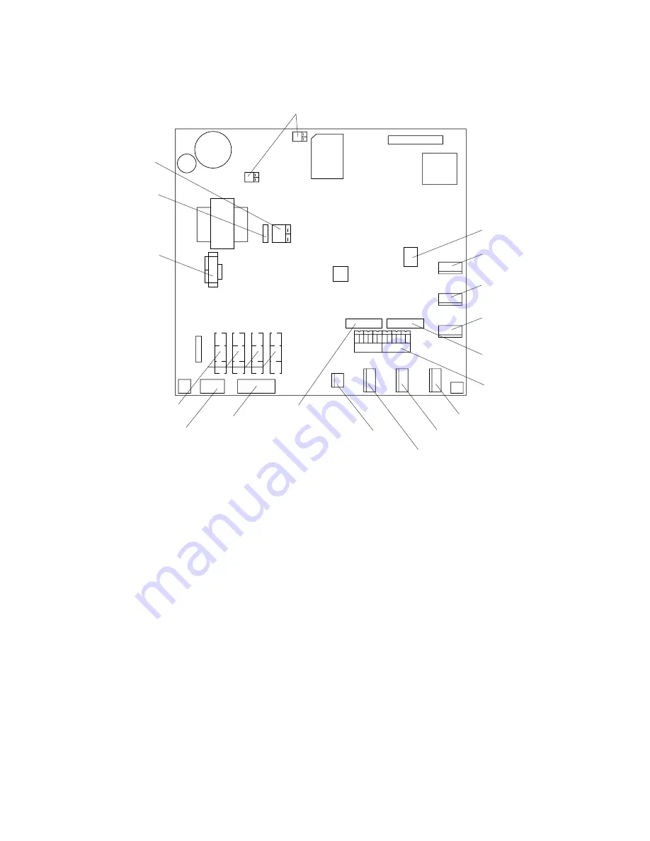
Location of DIP switches, jumper wires on the GYRO CONVERTER
Board

64P1106

JP5, JP4
(Supply voltage)

JP2

(Rotor voltage)

JP3

(Stator voltage)

JP1

(Gyro type)

Fuse

(2A)

J5
(Rotor signal input,
external power input)

J4
(Stator signal input)

SW1
DIP switch

J6

(IEC-61162-1 output port)

J7

(Data output port #1)

J8
(Data output port #2)

J9
(Data output port #3)

JP6, JP7
(AD formal
data Tx interval)

SW2
DIP switch

J10 
(Data output 
port #4)

J11
(Data output 
port #5)

J12
(Data output
port #6)

SW3
DIP switch

Figure 4-4 GYRO CONVERTER Board

Setting the heading readout on the radar display

Confirm that the gyrocompass is giving a reliable readout. Then, set the heading
readout on the radar display with the gyrocompass readout as follows:

1. Press [RADAR MENU] to display the FUNCTIONS 1 menu.

2. Press the [0] key twice to display the FUNCTIONS 3 menu.

3. Press the [9] key to select the GYRO SETTING option.

4. Rotate the EBL control to align the radar’s HDG readout with the gyrocompass.

5. Press [ENTER] to conclude the setting.

Summary of Contents for FR-2135S

Page 1: ......

Page 2: ... 4200 FIRST EDITION FIRST EDITION OCT OCT 1998 1998 Printed in Japan Printed in Japan All rights reserved All rights reserved L L JUL JUL 10 2003 10 2003 PUB No PUB No IME 34690 L IME 34690 L 00080839301 00080839301 00080839301 00080839301 TENI TENI FR 2135S FR 2135S 0 0 0 8 0 8 3 9 3 0 1 0 0 0 8 0 8 3 9 3 0 1 IME34690L00 IME34690L00 IME34690L00 IME34690L00 I M E 3 4 6 9 0 L 0 0 I M E 3 4 6 9 0 L ...

Page 3: ...0 0 1 2 t n i o p o t e c n a t s i D m W 0 1 2 t n i o p S 5 3 1 2 R F F A 0 3 N S m 7 0 F A 6 3 N S m 5 0 Do not open the equipment unless totally familiar with electrical circuits and service manual Only qualified personnel should work inside the equipment Wear a safety belt and hard hat when working on the scanner unit Serious injury or death can result if someone falls from the radar scanner ...

Page 4: ...Standard compass 1 70 m 0 90 m 5 00 m 2 80 m Steering compass 0 50 m 0 30 m WARNING Be sure that the power supply is compatible with the voltage rating of the equipment Connection of an incorrect power supply can cause fire or equipment damage The voltage rating of the equipment appears on the label above the power connector Use only the specified power cable Fire or equipment damage can result if...

Page 5: ...Tuning Initialization 3 1 3 2 Accessing Menus for Initialization and Adjustment 3 1 3 3 Adjusting Video Signal Level 3 1 3 5 Adjusting Sweep Timing 3 3 3 6 Suppressing Main Bang 3 3 3 7 Confirming Magnetron Heater Voltage 3 4 3 8 Initial Setting Menus 3 5 INSTALLATION OF OPTIONAL EQUIPMENT 4 1 Gyro Converter GC 8 4 1 4 2 ARP Board ARP 26 4 7 4 3 RP Board RP 26 4 10 4 4 Performance Monitor PM 50 4 ...

Page 6: ... i t a l l a t s n I s l a i r e t a M 0 0 0 0 2 3 0 P C 9 9 6 7 8 0 0 0 0 1 5 0 1 9 1 3 0 P C 3 0 6 4 1 3 0 P C e l b a c l a n g i S 7 0 9 3 1 3 0 P C m 5 1 5 1 4 7 3 0 S S E E P A C K I N G L I S T S 0 1 0 0 2 3 0 P C 0 0 7 7 8 0 0 0 0 5 0 1 9 1 3 0 P C 3 0 6 4 1 3 0 P C e l b a c l a n g i S 7 0 9 3 1 3 0 P C m 0 2 0 2 4 7 3 0 S 0 2 0 0 2 3 0 P C 1 0 7 7 8 0 0 0 0 5 0 1 9 1 3 0 P C 3 0 6 4 1 3...

Page 7: ...r o f 2 2 5 6 U R 0 1 4 0 3 0 0 0 0 1 V 0 2 2 3 V 0 0 2 φ t i n u r e n n a c s r o f 5 0 3 3 U R 8 4 4 0 3 0 0 0 0 1 r e c i e d r o F 1 6 6 4 5 U R 3 5 4 0 3 0 0 0 0 1 V 0 4 4 3 V 0 0 2 φ t i n u r e n n a c s r o f t i K n o i t a l l a t s n I M P 0 5 1 3 0 P O 0 9 4 5 8 4 8 0 0 t e s 1 A P R A 6 2 P R A 0 0 5 5 8 4 8 0 0 t e s 1 r e t t o l P o e d i V T 6 2 P R 0 1 5 5 8 4 8 0 0 t e s 1 e p ...

Page 8: ... 60 Hz SHIP S MAINS POWER SUPPLY UNIT PSU 004 Gyro Converter GC 8 Gyrocompass 100 110 115 220 230 VAC 1φ 50 60 Hz For DISPLAY UNIT For SCANNER UNIT 100 VAC 1φ 50 60 Hz For DE ICER 220 VAC 3φ 60 Hz 200 VAC 3φ 50 Hz RU 5693 110 VAC 3φ 60 Hz RU 6522 220 VAC 3φ 50 Hz RU 5466 1 440 VAC 3φ 50 Hz 440 VAC 3φ 60 Hz 380 VAC 3φ 50 Hz RSB 0026 0031 RSB 0088 0089 0090 For HSC For HSC 220 VAC 3φ 50 Hz 220 VAC 3...

Page 9: ...ignal cable near other onboard electrical equipment Also avoid running the cable in parallel with power cables A magnetic compass will be affected if placed too close to the scanner unit Observe the following compass safe distances to prevent deviation of a mag netic compass Standard compass 5 0 m Steering compass 2 80 m Do not paint the radiator aperture to ensure proper emission of the radar wav...

Page 10: ...bration and rolling exerting excessive levels of stress at the base of the radiator which can damage the radiator To prevent this relocate the scanner unit or if relocation is not possible reinforce the platform EXAMPLE Mount the scanner unit Directly on the mast or on the platform as near as possible to the center of the mast Pole for DF etc Mounting position Remarkable vibration pitching Pole fo...

Page 11: ... B 1 8m Lifting fixture Collar for fixing Supplied as installation materials Remove after installation Hex bolt M12X20 Spring washer M12 Remove lifting fixture coat threads of hex bolts with silicone grease and then insert bolts in scanner body Lifting hook 2 pcs Figure 1 2 Attachment of lifting fixtures and collar Protect radiator with cardboard or cloth at locations marked with asterisk A 2 0m B...

Page 12: ...iator bracket Radiator direction is shown by the logo on the bracket If reversely oriented the radiator cannot be set to the bracket 5 Loosely fix the radiator to the radiator bracket with hex bolts M10 x 25 spring washers and flat washers 6 Remove the guides pins and tighten hexagon bolts Scanner radiator Do not remove the teflon tube from the center conductor Guide pin 2 pcs Instruction label fo...

Page 13: ...EW Figure 1 5 Installation of reinforcement ribs 2 Place the corrosion proof rubber mat supplied on the mounting platform 3 Hoist the scanner unit as shown on page 1 3 and place it on the rubber mat Orient the cable gland toward the ship s stern or port starboard Remove the lifting fixtures and collars 4 Fix the scanner base to the mounting platform with four M12x70 hex bolts nuts washers and seal...

Page 14: ...ealant Ground wire Welding Hex nut Ground terminal provided on scanner base Set corrosion proof rubber mat bolt scanner unit to mounting location and coat exposed hardware with silicone sealant Arrange ground terminal as close as possible to scanner unit Spring washer Flat washer Hex bolt Flat washer Spring washer Flat washer Use two nuts Figure 1 6 Mounting of scanner unit ...

Page 15: ... vibration which is normally experienced on the ship If necessary reinforce the mounting location Determine the mounting location considering the length of the signal cable be tween the scanner unit and the display unit and the power cable between the display unit and Power Supply Unit PSU 004 Leave sufficient space on the sides and rear of the unit to facilitate mainte nance Also leave a foot or ...

Page 16: ...ws a Raise the stay as shown below Stay HORIZONTAL WARNING Possibility of injury Hold handle when mounting display unit Display unit may fall Lock stay before servicing Two warning labels on the underside of monitor WARNING Figure 1 9 Display unit inside view b While pushing the stopper set the catch on the display unit in the hole at the front edge of the stay CAUTION Use two people to complete t...

Page 17: ...t at the rear fixing holes while the monitor is raised 7 Retract the stay and lower the monitor 8 Fasten the display unit to the mounting locations at rear fixing holes 2 points with M10 bolts nuts and flat washers using the pipe box spanner supplied The rear left hole is hid under the PTU cover Remove the cover as follows 1 Unfasten five M3x8 screws at the top of the PTU cover and two M4x8 screws...

Page 18: ...ugh the deck referring to the outline drawing at end of this manual 2 Open the front cover 3 Fix the equipment with M12 bolts nuts and washers 4 Hoist the console to the deck by using the eye bolts attached to the console Remove the eye bolts and set the cosmetic caps to the eye bolt holes Separating the control head The control head connects to the display unit with a connection cable thus it can...

Page 19: ... 2 3 6 1 4 4 1 3 0 1 1 4 0 8 6 2 0 0 1 B K r e v o c t s u D 3 9 6 1 4 4 1 3 0 1 0 6 7 1 7 2 0 0 1 w e r c S 0 1 x 4 M 3 6 4 4 1 8 8 0 0 0 l e b a L 1 1 0 1 3 0 0 6 8 1 0 3 2 6 3 2 0 0 1 r e b b u R p i h s n o N 4 9 6 1 4 4 1 3 0 1 0 6 7 1 7 2 0 0 1 Display unit modification procedure 1 Raise the monitor unit referring to procedure for tabletop mounting on page 1 8 2 Unplug two connectors from th...

Page 20: ... monitor unit 8 Unfasten four screws fixing the right and left brackets on the control head 9 Unfasten four screws fixing the right and left covers of the display unit 10 Unfasten six screws fixing the right and left KB arms 11 Unfasten three screws fixing the panel cover KB arm L 03 144 1341 M5X25 SUS 3 pcs Panel cover 03 144 1345 M4X10 3 pcs Control head M5X25 SUS 4 pcs M5X25 SUS 3 pcs KB arm R ...

Page 21: ...om plate of the control head to dismount the handle 4 Replace the cable assy with cable assy UL2464SB2 0P 1P 10 m supplied as below and reassemble the control head 5 Paste warning label to the bottom plate KB BOTTOM PLATE P312 FX Connector P314 XH3P J312 underside J314 underside Lay cable in slot Screw M4X8 8 pcs Pan head Screw M4X8 2 pcs Be careful not to pinch cable between KB clamp and spacer S...

Page 22: ... screw for the panel cover 10 Attach rubber to feet to the bottom of the keyboard if the keyboard is not going to be permanently fixed To fix the keyboard to a desired location fasten the KB fixing plate to the keyboard and desired location with two upset screws M5X25 formerly used to fasten KB arms and two tapping screws φ6 5 local supply as below KB Fixing Plate KB Fixing Plate CONTROL HEAD SIDE...

Page 23: ...in vertical or horizontal posi tion For the console mount display unit the PSU 004 can be installed inside the console However select a dry and well ventilated location and observe the com pass safe distances below to prevent deviation of a magnetic compass Standard compass 0 50 m Steering compass 0 30 m Fasten the unit to chosen location with four M6 screws ...

Page 24: ...This page is intentionally left blank ...

Page 25: ... 4 Remove insulation of cores by about 10 mm Fix crimp on lugs to the cores and armor 5 Cover the armor with vinyl tape leaving the portion which will lie inside the cable clamp untaped 40 mm Lay this part in cable clamp Taping a b d Vinyl sheath 5 mm Armor DPYCY 3 5 10 mm c About 80 mm Core S 3 5 mm 2 4 mm 2 Armor Vinyl sheath DPYCY 3 5 sectional view Figure 2 1 Fabrication of power cable DPYCY 3...

Page 26: ...olt M5X35 SUS 2 pcs A Rear clamp base B Power clamp Aluminum C Signal clamp Aluminum D Rear clamp plate B Power clamp Aluminum C Signal cable Aluminum D Rear clamp plate A Rear clamp base Cable position in clamp Display unit rear view PWR SCAN Log Keyboard Navigation Nav equipment Gyrocompass Slave display External CRT Rear cable entrance Cable Shielding foam Display unit right hand side view Disp...

Page 27: ...through the cable clamp at the rear of the console and ground their shields in the cable clamp For signal cable remove vinyl sheath where cable lies in cable clamp Fasten cables with cable ties Close shutter and cover with aluminum tape to keep foreign objects out of the display unit SIGNAL CABLE Remove the vinyl sheath here 1300 mm from display unit end of cable remove sheath by 70 mm Seventh hol...

Page 28: ...ance always ON J448 DJ1 J467 J446 J448 J445 J449 J465 J455 J466 J454 J450 J462 J456 J453 J451 J458 J457 J452 J442 J443 J444 J463 Connect coax cable here Fasten TX HV line to 1 termanal To fasten 1 Slide terminal 2 Lift terminal to remove Location of connectors on the INT Board See next page for connector description Fix the DJ1 connector with teo M3x8 screw supplied Ground terminal Tabletop type F...

Page 29: ... 4 J n i p 8 H N 1 4 1 D C 0 4 1 D C 0 0 5 D G 2 K M 0 0 5 D G 0 0 8 D M F 0 8 D M F 1 1 0 r o f t i n u y a l p s i D 1 s e i r e s 5 0 1 2 R F d e s u e b n a c r a d a r y a l p s i d e v a l s s a t i n u g n i r a e b g n i d a e H r e g g i r t x T o e d i v l a n g i s r e z z u B Z U B T X E 1 5 4 J n i p 9 H N p m a w r e k a e p S l a n g i s r e k a e p S l a n g i s r o t i n o M 9 4 4...

Page 30: ...or 2 2 Scanner Unit Fabricating multicore cable 660V MPYCY 12 250V MPYCY 12 JIS cable 1 Shorten the multicore cable making the length from the cable gland to the cable end inside the scanner unit 450 mm Remove the vinyl sheath of the cable by 450 mm the armor by 440 mm Armor 440 mm 450 mm Conductors Armor Vinyl sheath Core φ 1 25 mm2 Figure 2 7 Fabrication of multicore cable 660V MPYCY 12 250V MPY...

Page 31: ...k armor by 5 mm and pass it through the two flat washers as shown in Figure 2 9 Armor folded back Gasket Seal with putty after tightening Vinyl sheath Clamping gland Flat washer Cable gland Flat washer Flat washer Figure 2 9 Passing clamping gland washers and gasket on the multicore cable 7 Shorten conductors considering their locations on the terminal board STB 1 RTB 801 STB 1 Figure 2 10 Scanner...

Page 32: ...40 mm Approx 550 mm Anti corrosive vinyl sheath Armor Approx 540 mm Inner shield Outer shield Figure 2 11 Fabricating the signal cable S03 74 15 Unravel the outer shield with a screwdriver or similar tool to expose the cores beneath the outer shield Similarly expose the cores beneath the inner shield Mark all cores for future identification 16 As shown in Figure 2 12 slide the clamping gland washe...

Page 33: ... 9 Terminal board fixing plate for RTB 801 Ground terminal Figure 2 13 Scanner unit rear view Locking wire saddle Figure 2 14 Scanner unit rear view 19 Fasten the terminal board fixing plate for RTB 801 ...

Page 34: ...h conductor and fix the crimp on lug FV1 25 M3 Red to each conductor As shown in Fig ure 2 14 fold back the coaxial cable four times and attach the crimp on lug FVD1 25 3 ø3 red Attach the crimp on lug FVD1 25 ø3 red to the shield 23 Tighten the clamping gland and then seal the cable gland with putty 24 Fasten the shield to the ground terminal on the scanner unit chassis 25 Connect conductors to t...

Page 35: ...play unit from 100 VAC or 220 VAC power add or delete jumper wires on the PTU Board and change the power fuses inside the display unit as shown in the table below The figure below shows the location of the power fuses and the jumper wires on the PTU Board Table 2 2 Jumper wire setting on the PTU board fuse rating and power specification B C P c e p S r e w o P a n n e t n A m p r 1 P J 2 P J 3 P J...

Page 36: ...s p i h S t i n U r e n n a c S 2 K y a l e R l a m r e h T e p y T g n i t a R 3 C A V 0 2 2 0 0 2 φ 6 2 0 0 B S R A 7 1 3 H N 0 R T A 3 2 3 C A V 0 4 4 0 8 3 φ 1 3 0 0 B S R A 8 0 3 H N 0 R T A 0 1 3 C A V 0 2 2 φ z H 0 5 8 8 0 0 B S R A 7 1 3 H N 0 R T X A M A 6 2 3 C A V 0 2 2 φ z H 0 6 9 8 0 0 B S R A 7 1 3 H N 0 R T X A M A 6 2 3 C A V 0 4 4 φ z H 0 6 0 9 0 0 B S R A 8 0 3 H N 0 R T X A M A ...

Page 37: ...menu and 0 again 2 Press the 0 key 3 Press the ENTER key five times and turn the power off and on again 4 Initializing appears during restoring It takes about 90 seconds to restore the default settings after which the normal display appears Confirm that 2 MODEL is set to OTHER S BND in the INITIAL SETTING 4 menu 3 3 Adjusting Video Signal Level When the signal cable is very long the video amplifie...

Page 38: ...anner mounted error to port HDG SW advanced Picture appears deviated clockwise Apparent position of target 000 010 020 030 040 050 060 070 080 090 100 110 120 130 140 150 160 170 180 190 200 210 220 230 240 250 260 270 280 290 300 310 320 330 340 350 b Target b Apparent position of target Scanner mounted error to starboard HDG SW delayed Picture appears deviated counterclockwise Correct bearing re...

Page 39: ... MENU 0 0 0 2 3 to select TIMING ADJ on the INITIAL SETTING1 menu 2 Transmit on the 0 25 nm range 3 Adjust radar picture controls to display picture properly 4 Select a target echo which should be displayed straightly 5 Adjust the VRM control to straighten the target echo 6 Press ENTER 3 6 Suppressing Main Bang If main bang appears at the screen center suppress it as follows 1 Turn on the power Tr...

Page 40: ... the TX option 4 Turn off the antenna switch in the display unit 5 Connect a multimeter set to the 10 VDC range between 12 of P801 and the chassis 6 The multimeter should read 9 2 9 4 V If not adjust VR1 7 Transmit on the 48 mile range 8 The multimeter should read 7 3 8 3V 9 Press RADAR MENU 0 0 0 2 0 5 to select the 5 SCANNER STOPPED field and the ROTATE option 10 Turn on the ANT MOTOR SW on the ...

Page 41: ...L SETTING menu four menus and the OWN SHIP INFORMATION menu setup the radar according to expected usage authorities specification ship s characteristics operator s preference etc Set items on each menu in accor dance with regulations operator s preference After entering initial settings reset the power ...

Page 42: ...OFF ON 9 INDEX LINES 2 3 6 0 INITIAL SETTING 4 INITIAL SETTING 4 1 INITIAL SETTING 3 2 MODEL FR 2115 2125 OTHER X BND FR 2165DS 2135SW OTHER S BND 3 TYPE R N G D 4 CTR STC CURVE L M H 5 RJ 7 OFF ON 6 RJ 8 OFF ON ANT A FR 2115 2125 OTHER X BND FR 2165DS 2135SW OTHER S BND ANT B FR 2115 2125 OTHER X BND FR 2165DS 2135SW OTHER S BND 7 SHIP S TYPE DEEP SEA FISHING LONG LINE FISHING 8 9 CABLE LENGTH 50...

Page 43: ...rength echo DISPLAY Select radar display function main or sub slave SECTOR BLKG Sets area up to 2 where no radar pulses will be transmitted For example set the area where an interfering object at the rear of the scanner would produce a dead sector area where no echoes appear on the display To enter an area select ON and enter relative bearing range of the area INITIAL SETTING3 menu Keying sequence...

Page 44: ...t class of vessel deep sea fishing long line fishing CABLE LENGTH Set for 500 FACTORY DEFAULT Restores all menus default settings OWN SHIP INFORMATION menu Keying sequence RADAR MENU 0 0 0 2 6 SHIP S LENGTH Enter ship s length SHIP S WIDTH Enter ship s width RADAR POSN Enter distance from both bow and port to the radar antenna location NAV ANT POSN Enter distance from both bow and port to the navi...

Page 45: ...allation and connection of the GYRO CONVERTER Board Necessary Parts GC 8 2 008 446 520 e m a N e p y T y t Q o N e d o C d r a o B r e t r e v n o C o r y G 6 0 1 1 P 4 6 1 0 2 2 2 1 4 4 0 0 s w e r c S W 0 0 7 2 C 8 x 3 M 5 4 0 4 1 8 8 0 0 0 r e k c i t S 1 1 2 0 2 4 1 0 4 6 1 1 0 7 2 3 1 0 0 1 1 Turn off the power 2 Open the display unit See Chapter 1 for instructions 3 Fasten the GYRO CONVERTER...

Page 46: ...ocompass specifications and set up the DIP switches and jumper wires on the GYRO CONVERTER Board according to gyrocompass connected Setting jumper wires and DIP switches by gyrocompass specifications page 4 3 Setting jumper wires and DIP switches by make and model of gyrocompass page 4 5 Location of jumper wires and DIP switches page 4 6 6 Solder the gyrocompass cable to the VH connector assemblie...

Page 47: ...oard DIP switch jumper wire settings Default setting The default setting of all DIP switches is off and all jumpers wire are set to 1 Note that jumper wire JP1 is set at 1 2 and 3 In those settings the gyrocom pass having the following characteristics can be directly connected modification of the GYRO CONVERTER Board is not necessary AC synchronous signal 50 60 Hz Rotor voltage 60 V to 135 V AC St...

Page 48: ...to 70 VAC OFF 2 40 V to 90 VAC ON 1 20 V to 45 VAC or 20 V to 60 VDC OFF OFF 2 60 V to 135 VAC OFF 1 40 V to 90 VAC ON OFF 1 60 V to 135 VAC OFF OFF 1 5 Ratio 6 Supply voltage Ratio SW1 1 SW 1 2 SW1 3 Supply voltage JP4 JP5 360x OFF OFF OFF 20 V to 45 VAC or 20 V to 60 VDC 2 2 180x ON OFF OFF 90X OFF ON OFF 30 V to 135 VAC or 40 V to 100 VDC 1 1 36X ON ON OFF 7 AD 10 format data Tx interval 9 NMEA...

Page 49: ...5 e g a t l o v r o t o R V 8 6 e g a t l o v r o t a t S x 0 6 3 F F O F F O F F O F F O F F O F F O F F O F F O F F O F F O F F O 1 3 2 2 2 1 1 c e m i k o T y r r e p S e p y t 1 1 2 1 S E 2 0 1 1 0 1 T L G 7 0 1 K 6 0 1 3 0 1 s u o n o r h c n y s C A z H 0 6 0 5 V 0 1 1 0 0 1 e g a t l o v r o t o R V 0 9 e g a t l o v r o t a t S x 6 3 N O N O F F O F F O F F O F F O F F O F F O F F O F F O ...

Page 50: ...10 Data output port 4 J11 Data output port 5 J12 Data output port 6 SW3 DIP switch Figure 4 4 GYRO CONVERTER Board Setting the heading readout on the radar display Confirm that the gyrocompass is giving a reliable readout Then set the heading readout on the radar display with the gyrocompass readout as follows 1 Press RADAR MENU to display the FUNCTIONS 1 menu 2 Press the 0 key twice to display th...

Page 51: ... N e p y T y t Q o n e d o C d r a o b P R A B 2 0 0 9 P 8 1 1 0 5 6 3 7 4 8 0 0 Installation of the ARP board 1 Remove the bottom cover of the display unit by unfastening four screws 2 Set the ARP Board in the center slot of the PCB card case PCB card case Top RP Board Option Middle ARP Board Option Bottom SPU Board Figure 4 5 Display pedestal inside view 3 Adjust the ARP referring to the procedu...

Page 52: ...P Board so the multimeter reads between 0 09 and 0 14 VDC 4 Set controls and switches as below GAIN fully clockwise max Interference rejector OFF Range 24 nm Echo stretch OFF 5 Press RADAR MENU 0 0 0 0 open the INITIAL SETTING3 menu 6 Set the VIDEO SIG field to DIGITAL and press ENTER 7 Adjust R103 on the ARP Board so noise just appears on the display Too little noise Proper noise Too much noise F...

Page 53: ...smit state Confirm that LEDs CR9 CR10 CR11 CR12 CR15 and CR16 on the ARP Board are off If ship s speed is zero or other signal is not being input correspond ing LED will light S1 CR16 LOG CR15 GYRO CR9 HDG CR10 BRG CR11 VID CR12 TRG 4 3 2 1 F F O F F O F F O F F O Figure 4 8 ARP Board ARP 26 ...

Page 54: ...A w e r c s d a e h n a P W 0 0 7 2 C 5 x 6 2 M 2 3 7 9 0 0 8 0 0 0 r e h s a w k c o l d e h t e e T h t e e t e d i s t u O W 1 9 1 5 C 4 M 1 6 0 5 4 6 8 0 0 0 y s s a e l b a C 2 5 A A D 0 0 1 6 F I H 1 3 5 5 7 3 1 0 0 0 1 Lift the monitor and fix it with the stay Refer to Chapter 1 for instructions 2 Remove the right arm cover from the control head 3 Fasten the card case to the right arm cover...

Page 55: ... page 4 7 for the location of the pcb card case 7 Run the connector from the card case in front of the GYRO CONVERTER Board 8 Plug the connector in J1 on the RP Board 9 Fasten the ground wire from the connector at the location shown below INT Board GYRO CONVERTER Board FRONT Fasten ground wire from connector to this screw RP connector TOP VIEW FRONT VIEW RP Board ARP Board SPU Board Route cable be...

Page 56: ...n a P W 0 0 7 2 C 8 x 4 M 1 5 4 4 1 8 8 0 0 0 B w e r c S d a e H n a P W 0 0 7 2 C 8 x 3 M 2 4 0 4 1 8 8 0 0 0 A w e r c S d a e H n a P W 0 0 7 2 C 5 x 6 2 M 2 3 7 9 0 0 8 0 0 0 1 Lift the monitor See Chapter 1 for instructions 2 Fasten the mounting base with one M4 x 8 screw as below Fasten with M4 x 8 screws Fasten with M3 x 8 screws 2 pcs Figure 4 12 Display unit inside view 3 Fix the mountin...

Page 57: ...e top slot of the pcb card case 7 Run the connector from the card case in front of the GYRO CONVERTER Board 8 Plug the connector in J1 on the RP Board 9 Fasten the ground wire from the connector at the location shown below INT Board GYRO CONVERTER Board FRONT Fasten ground wire from connector to this screw RP connector TOP VIEW FRONT VIEW RP Board ARP Board SPU Board Route cable between ARP and SP...

Page 58: ...monitor See Chapter 1 for instructions 2 Fasten the PM Board 03P9225 to the location shown below with three screws M3 x 8 J401 J411 PM Board 03P9225 J403 J402 Figure 4 15 Display unit inside view 3 Connect the connector P401 coming from J411 to J401 on the PM Board 4 Connect two connector assemblies VH3P L300 AA to J402 and J403 5 Solder the other end of there connector assemblies with external ca...

Page 59: ...onitor and fix it with the stay See page 1 5 for instructions 2 Unfasten four screws to dismount the shield cover for the INT Board 3 Fasten the ALARM Board to the display unit with four pan head screws M3X8 supplied 4 Connect the NH connector 9 9P supplied between J471 on the ALARM Board and J451 EXT BUZ on the INT Board passing it through the cable band and binding it with existing cable tie 5 F...

Page 60: ...crew M4X12 Cable Band HP 3N INT Board 03P9252 NH Connector 03 1990 9 9P Pass cable through here Existing cable tie Figure 4 16 Display unit inside view 20 mm Shrink Tubing HOW TO INSULATE THE POWER CABLE 2 Solder power cable to signal cable 3 Heat shrink tubing with solder ing iron Solder 1 Make length of shrink tubing 20 mm slip tubing onto wiring ...

Page 61: ......

Page 62: ......

Page 63: ......

Page 64: ......

Page 65: ......

Page 66: ......

Page 67: ......

Page 68: ......

Page 69: ......

Page 70: ......

Page 71: ......

Page 72: ......

Page 73: ......

Page 74: ......

Page 75: ......

Page 76: ......

Page 77: ......

Page 78: ......

Page 79: ......

Page 80: ......

Page 81: ......

Page 82: ......

Reviews: