background image

1. OPERATIONAL OVERVIEW 


1-40 

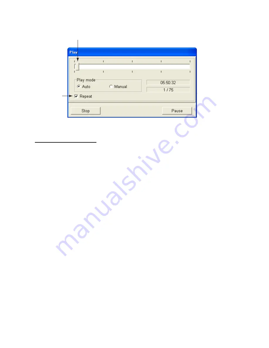
11. Click the Open button to start playback. 

Sliding bar

Check to
repeat
playback.


Play dialog box 


Notes on playing back data 

• 

Use the Play Mode Manual and Play Mode Auto radio buttons to change setting data: 
Auto: Use settings used at the time of the recording.   
Manual: Apply current settings. 

• 

To playback a file manually, use the sliding bar to choose the location where to start 
playback and then hit the Restart button. 

• 

Click the Pause button to temporarily stop playback. To restart playback use the Restart 
button.  

• 

Use the Stop button to stop playback.


Summary of Contents for FCV-30

Page 1: ...COLOR SOUNDER FCV 30 ...

Page 2: ...8 65 2111 0798 65 2111 Fax Fax 0798 65 4200 0798 65 4200 FIRST EDITION FIRST EDITION FEB FEB 2005 2005 Printed in Japan Printed in Japan All rights reserved All rights reserved D D MAY MAY 16 2006 16 2006 Pub No Pub No OME 23730 OME 23730 00015183503 00015183503 00015183503 00015183503 DAMI DAMI FCV 30 FCV 30 0 0 0 1 5 1 8 3 5 0 3 0 0 0 1 5 1 8 3 5 0 3 OME23730D00 OME23730D00 OME23730D00 OME23730D...

Page 3: ...The example screens or illustrations shown in this manual may not match the screens you see on your display The screen you see depends on your system configuration and equipment settings This manual is intended for use by native speakers of English FURUNO will assume no responsibility for the damage caused by improper use or modification of the equipment or claims of loss of profit by a third part...

Page 4: ...sh leaks into the equipment Fire or electrical shock can result if water leaks in the equipment WARNING Keep heater away from equipment A heater can melt the equipment s power cord which can cause fire or electrical shock Use the proper fuse Fuse rating is shown on the equipment Use of a wrong fuse can result in damage to the equipment Do not operate the equipment with wet hands Electrical shock c...

Page 5: ...avigated while monitoring the depth indication since it is not updated when the picture is stopped Set the gain properly No picture appears if the gain setting is too low and noise appears when the gain is too high If the gain is set improperly the depth indication may be wrong resulting in a potentially dangerous situation if the vessel is navigated by monitoring the depth indication Gain too hig...

Page 6: ...m 1 18 1 12 Setting Measuring Area 1 20 1 12 1 Measuring fish in a specific location 1 20 1 12 2 Measuring fish in all areas 1 21 1 12 3 Measuring fish in a specific depth range 1 21 1 12 4 Measuring bottom fish 1 21 1 13 Suppressing Low Level Noise Clutter suppression 1 23 1 14 Eliminating Weak Echoes 1 24 1 15 Suppressing Unwanted Noise 1 24 1 16 Picture Advance Speed 1 25 1 17 A scope Display 1...

Page 7: ...Mode Dialog Box 3 1 3 2 Display Item Dialog Box 3 3 3 3 Echo Image Dialog Box 3 4 3 4 Multi beam Dialog Box 3 6 3 5 Temp Dialog Box 3 7 3 6 Color Dialog Box 3 8 3 7 Unit Dialog Box 3 10 3 8 Target Sphere Calibration Dialog Box 3 11 3 9 External Echo Sounder 3 13 3 9 1 Displaying image from external echo sounder 3 13 3 9 2 File menu 3 14 3 9 3 Display menu 3 15 3 9 4 Setting menu 3 17 3 9 5 System ...

Page 8: ...high performance echo sounder designed for fishing as well as oceanographic research Its newly developed multi beam transducer provides multi directional and long range detection Consisting of a processor unit control unit transceiver unit and transducer the FCV 30 provides high definition underwater images on the monitor of your choice The main features of the FCV 30 are Stabilization compensatio...

Page 9: ...0 VAC 1φ 50 60 Hz 100 120 200 240 VAC 1φ 50 60 Hz Transceiver Unit CV 302 Junction Box option CV 304 Transducer CV 303 Monitor Unit MU 151C MU 201C option OR commercially available monitor Navigator Satellite Compass Net Sonde Hard Disk USB Memory Network Sounder ETR 30N System configuration ...

Page 10: ...viii This page intentionally left blank ...

Page 11: ...ls F1 F3 F4 F2 Turns the power on off User programmable function keys Left button Confirms menu selection Right button Displays pop up menu Trackball Moves trackball pointer Thumbwheel Shifts cursor position in setting window Control unit ...

Page 12: ...ll pointer File Disp Setting System Window Marker line Monday April 10 2006 15 01 Date and time Menu bar 1 Roll the trackball to choose menu desired File Disp Setting System etc from the menu bar at the top of the screen and the click it with the left button Ellipsis indicates a dialog box is available Setting menu 2 Roll the trackball to choose menu item desired and then click with the left butto...

Page 13: ...setting using radio buttons Enabled Disabled Radio buttons Click the item desired A black dot appears when the item selected is enabled Changing setting using a list box Normal List box 1 Click in the list box or click the box itself to show a list of options 2 Click the desired setting Changing setting using a spin box Spin box A setting may be changed from a spin box two ways depending on conten...

Page 14: ...check box of the item you want to enable or disable 2 Push the left button to remove or insert the check mark as appropriate An item is enabled when the check mark is present Changing setting using a toggle button Enabled highlighted in blue Disabled 1 Click the item desired 2 Each click enables or disables your selection alternately When the item selected is enabled it is highlighted in dark blue...

Page 15: ...cording to item selected Operation from an options window Roll the trackball to execute appropriate operation and then push the left button Operation from a setting window There are three settings methods Drag the sliding bar Place the pointer on the sliding bar and hold down the left button while rolling the trackball Place the pointer on the track bar and then click with the left button With the...

Page 16: ... Note that the Windows Help feature is not available with this equipment Turning off the power There are two methods to turn off the power a Press the switch Do not press the switch more than four seconds last used settings will not be memorized b Click the close button The following window appears Then click the Yes button to quit Are you sure to quit Yes Shutdown No Cancel Yes No Confirmation Sh...

Page 17: ...rt transmitting and receiving after turning on the power 1 Click File File menu 2 Click TX Start Transmission starts and images from underwater appear To stop transmission choose TX Stop at step 2 It is recommended that after stopping transmission wait three seconds before using the menu ...

Page 18: ...e dialog box 3 In the Display Mode window choose the mode you wish to use See the next several sections for display descriptions To divide the screen go to step 4 Otherwise go to step 5 4 In the Screen Layout window click the screen division you wish to use The Preview window shows the results of your selection Note that the split beam display cannot be divided 5 Click the OK button to finish ...

Page 19: ...M marker Elapsed time and postion of vertical VRM Measuring range TS 20 40 60 80 0 60 00 00 28 34 42 616 N 135 19 740 E Vertical VRM Net marker 4 0 2 0 0 0 2 0 4 0 Temperature scale Temperature graph Depth scale Split beam display Note When the display range for the split beam presentation is 500 m or higher the indication Deep mode appears in the menu bar To enable deep mode detection click Deep ...

Page 20: ...60 80 0 Dividing line 15 3 0 3 Horizontal range from transducer Beam direction can be shown with an icon See paragraph 3 2 Three beam display Changing display area The width of each display can be adjusted as follows 1 Place the trackball pointer on a dividing line between displays and the pointer changes to a double ended arrow 2 Hold the left button while dragging the double ended arrow with the...

Page 21: ... value can be set between 100 and 5000 m For further details see page 3 6 Menu for turning simultaneous transmission on or off Simul TX Simultaneous transmission options 1 5 4 Split beam two beam display The split beam two beam display provides a split beam plus images captured from the port and starboard sides TS Split beam display B 270 0 T 10 0 B 90 0 T 10 0 20 40 60 80 0 20 40 60 80 0 20 40 60...

Page 22: ... the product of displays created with Display mode change button in the Mode window The default settings are as follows User 1 Split beam display User 2 3 beam port starboard and downward directions User 3 Split beam two beam port and starboard directions For how to customize the User displays see paragraph 3 1 ...

Page 23: ...in 12 preset choices The default ranges are shown in the table below Display ranges Display Range Unit 1 2 3 4 5 6 7 8 9 10 11 12 m 10 20 40 80 150 300 500 1000 1500 2000 2500 3000 Note You may set ranges as desired For further details see Chapter 3 1 Click Setting Setting menu 2 Click Echo image Echo image dialog box ...

Page 24: ...AL OVERVIEW 1 14 3 Click in the Range box Range options 4 Click the range you wish to use For example choosing 80 the display will show underwater conditions from the transducer down to 80 m 5 Click the OK button ...

Page 25: ... the display in order to look at a shallower or deeper depth without changing the current range Picture Shift the start depth to watch shallow or deep Shift principle 1 Click Setting 2 Click Echo image 3 Click or in the Shift box to choose shift value 4 Click the OK button ...

Page 26: ...reen Use the proper gain setting Incorrect gain may produce wrong depth indication possibly resulting in a dangerous situation CAUTION 1 Click Setting 2 Click Echo image 3 Click or in the Gain box to choose the gain setting desired Gain too high Gain proper Gain too low Examples of gain settings and resulting pictures 4 Click the OK button ...

Page 27: ...on with the VRMs Measuring depth 1 Roll the trackball to place the pointer on the horizontal VRM The shape of the pointer changes to 2 Hold down the left button while rolling the trackball upward or downward to place the horizontal VRM on the object that you wish to measure the depth 3 Read the depth indication on the horizontal VRM Measuring elapsed time 1 Roll the trackball to place the pointer ...

Page 28: ... Note that color of the marker line can be changed For details see paragraph 3 5 1 11 Fish Size Histogram The fish size histogram display shows single fish size within the area measured You may set up this display as follows 1 Display the split beam display See paragraph 1 5 2 Click Disp 3 Click Display Window Display window dialog box 4 Click Fish size histogram The toggle button is then colored ...

Page 29: ...The fish size histogram window can be moved as desired For details see Chapter 2 Note 2 When the fish size histogram window is closed all data measured is deleted How to read the fish histogram The bar graph shows size and proportion of fish in measuring area The vertical axis shows fish length default setting and the horizontal axis shows distribution In the fish size histogram display above more...

Page 30: ... bottom in all directions Measure specific depth range Measure bottom fish 1 12 1 Measuring fish in a specific location 1 Click Setting 2 Click Fish size Click the Fish size histogram tab if necessary to show the fish size dialog box Fish size dialog box measurement If the Unit or Display dialog box is shown click the Measurement tab 3 Click in the Measuring area box Area options 4 Click Manual ...

Page 31: ...fish in all areas 1 Click Setting 2 Click Fish size 3 Click in the Measuring area box 4 Click All 5 Click the OK button 1 12 3 Measuring fish in a specific depth range 1 Click Setting 2 Click Fish size 3 Click in the Measuring area box 4 Click Specific range 5 Click the OK button 6 Use the trackball to place the pointer on the measurement area boundary line 7 Hold down the left button while rollin...

Page 32: ...rement range markers on the fish size display 8 Place the cursor on the measurement range marker 2 yellow vertical line The shape of the cursor changes from an arrow to double ended arrow 9 Using the left button drag the measurement range marker 2 to the location desired and the release the left button Measurement range marker 1 short yellow horizontal dash automatically traces the bottom ...

Page 33: ...Click Settings 2 Click Echo image 3 Click in the Clutter curve box Clutter curve options 4 Click the setting desired referring to the description below Standard With high clutter level setting strong colors are untouched while weak echo colors are suppressed Straight With high clutter level setting weak to strong echoes are suppressed by averaging OFF Clutter suppression function is disabled 5 Cli...

Page 34: ... stronger the echo that will be erased 4 Click OK button 1 15 Suppressing Unwanted Noise Noise from other echo sounder or electrical interference may show itself on the screen Use the noise limiter to suppress unwanted noise Interference from other sounder Electrical interference Examples of noise 1 Click Setting 2 Click Echo image 3 Click in the Noise limiter box Noise limiter options 4 Click the...

Page 35: ...t FAST SLOW The advancement speed may be set independent of or synchronized with ship s speed 1 Click Settings 2 Click Echo image 3 Click in the Picture advance box The fractions in the window denote the number of scan lines produced per transmission For example 1 8 means one scan line is produced every eight transmissions STOP freezes the display and it is convenient for observing an echo SYNC ad...

Page 36: ...ment of fish school size and abundance at any speed Note This feature is available with ship s speed between 2 and 20 kts If ship s speed is above or below those values the picture is advanced using the upper or lower limit whichever is closest to the actual ship s speed FULL SPEED HALF SPEED Actual Movement Same size fish schools Speed Normal Mode Speed Dependent Picture Advance Mode Fish school ...

Page 37: ... desired A scope display and then push the left button Small A scope display shown on right 1 10 of the screen Standard A scope display shown on right 1 8 of the screen Large A scope display shown on right 1 6 of the screen 4 Click the OK button Strong reflection bottom TS 20 40 60 80 0 40 00 00 28 34 42 616 N 135 19 740 E A scope display Strong reflection fish school Weak reflection small fish or...

Page 38: ...nge The audio alarm sounds and the visual alarm FISH appears in red reverse video and flashes when the bottom alarm is violated This alarm is useful when targeting a specific fish specie since each fish specie is known to inhabit certain depths Bottom fish alarm The bottom fish alarm sounds when a fish echo is within a predetermined distance from the bottom The audio alarm sounds and the visual al...

Page 39: ...rm choose alarm type with the radio buttons Fish or Bottom fish For the temp alarm or v temp alarm choose alarm type with the radio buttons Out of range or Within range 5 Click or in the Alarm depth box for bottom alarm or fish alarm or Temp limit box for temperature alarm or v temp alarm to set alarm depth or temperature limit 6 Click or in the Alarm zone box to set the width of the alarm from th...

Page 40: ...tem dialog box Alarm marker The alarm marker appears at the right edge of the display and the color is green for the bottom fish alarm and orange for the fish alarm To disable an alarm remove the check mark from the box at step 3 in the above procedure 1 18 3 Setting audio alarm volume You may set the volume of the audio alarm as follows 1 Click Settings 2 Click Alarm 3 Click in the Volume box 4 C...

Page 41: ...box F2 Shift dialog box F3 Gain dialog box F4 Mode dialog box 1 19 2 Programming the function keys 1 Press the appropriate function key until the menu title looks something like the one shown below Pressed function key File Disp Setting System Window FCV 30 F1 Key Registration 2 Click the item on the menu bar which you want to use For example Alarm in the Setting menu Note that neither Load user s...

Page 42: ...h species 1 20 1 Saving user settings 1 Adjust settings according to targeted fish or objective 2 Click File 3 Click Save user setting Selected dark blue Save area Scroll bar Save user setting 4 Click the or button to choose an empty save area The chosen save area is highlighted in dark blue You also may the scroll bar to choose a save Note If 20 areas are already saved choose an unnecessary one t...

Page 43: ...user settings while transmitting 1 Click File 2 Click Load user setting This window shows chosen display settings Thumbnail of display settings Read display 3 Click the or button to choose the display settings you wish to display The chosen display setting is highlighted in dark blue ...

Page 44: ...ls button to display detailed information about the chosen display settings This window shows display settings in detail Asterisk indicates saved display settings Details button Read display details shown 4 Click the Read button to activate chosen settings ...

Page 45: ...ser supplied to record and replay raw data and picture data Processor Unit USB Hard Disk USB 2 0 Power USB 1 1 Cannot be used Connecting a hard disk 1 21 1 Choosing where to record data 1 Connect a USB hard disk to the USB port on the processor unit 2 Click Setting 3 Click Record Not displayed during TX or RX Record dialog box ...

Page 46: ... file to find its size or recording time by clicking its check box to show the check mark 9 The size or recording time for the file selected appears in the Disk space info sub window To change the display content click Time or Size at Unit in the Disk space info sub window Deleting recorded data Data can be deleted from the Record window as follows 1 In the Data view sub window check the data you ...

Page 47: ...ile menu 3 Click Record When a file is recorded it is automatically assigned a file name comprised of date and time of the recording plus the extension lst An example file name is shown below 2005_03_01_05_50_32 lst Extension Seconds Minutes Hours Day Month Year To stop recording data choose Stop at step 3 in the above procedure ...

Page 48: ...disk to the USB port on the processor unit 2 Click File 3 Click TX Stop 4 Click File 5 Click Convert to HAC format Convert to HAC format dialog box 6 Click the Reference button 7 Choose the file LST file you wish to convert 8 Click the Open button C Documents and Settings FCV30 2005_03_01_05_50_32 hac Location of LST file Location of HAC file Total no of pings in lst file C Documents and Settings ...

Page 49: ...port on the processor unit 2 Click File 3 Click TX Stop 4 Click Play E Removable disk Open File location box File box Choosing file to replay 5 Click in the file location box 6 Click the hard disk drive connected to the FCV 30 Folder s showing year month and as folder name appear 7 Double click desired folder and EchoData folder appears 8 Double click the EchoData folder and hour minute second fol...

Page 50: ...Mode Auto radio buttons to change setting data Auto Use settings used at the time of the recording Manual Apply current settings To playback a file manually use the sliding bar to choose the location where to start playback and then hit the Restart button Click the Pause button to temporarily stop playback To restart playback use the Restart button Use the Stop button to stop playback ...

Page 51: ...mall thus loading time is much shorter 1 Connect a USB hard disk to the USB on the processor unit 2 Click File 3 Click Save the screen shot The screen shot is saved to the location designated at step 5 in paragraph 1 21 1 This data is automatically assigned a file name and extension as below 05_50_32 jpg Extension Seconds Minutes Hours File name for screen shot ...

Page 52: ... Click the hard disk drive connected to the FCV 30 Folder s showing year month and as folder name appear 6 Double click desired folder and ImageData folder appears 7 Double click the EchoData folder and hour minute folder appears 8 Double click the hour minute folder you wish to playback A list of JPG files appears 9 Click a JPG file to show file name in reverse video Chosen JPG file appears in th...

Page 53: ...1 OPERATIONAL OVERVIEW 1 43 11 To erase the screen shot click the Close button ...

Page 54: ...1 OPERATIONAL OVERVIEW 1 44 This page intentionally left blank ...

Page 55: ... on Window Displays 1 Click Disp Disp menu 2 Click Display Window One zoom window may be enabled Display window dialog box 3 Choose item s to enable or disable in the Display item window and then push the left button Items which are enabled are highlighted in blue and those which are disabled are grey Note Only one among bottom lock bottom zoom and marker zoom may be enabled 4 To change size of bo...

Page 56: ...enu bar Window currently displayed Click to bring window to front 2 Click Auto arrange to relocate windows to their default locations Moving windows 1 Use the trackball to place the pointer in the window 2 Roll the trackball while holding down the left button to move the window ...

Page 57: ... 32 77m 1 6 deg 2 1 17 8 34 21 5912 N 136 08 4732 E 13234 5 32234 7 32 7m 265 1deg Status ALARM PICTURE TIMER COURSE HEAVE GAIN SHIFT TEMPERATURE SPEED ROLL PITCH DEPTH LATITUDE P B LONGITUDE TD 17 8 00 10 40 6 13234 5 32234 7 34 21 5912 N 136 08 4732 E 32 7m 265 1deg 1 6 deg 2 1deg 32 77m DEPTH GAIN SHIFT ALARM PICTURE LATITUDE LONGITUDE TEMPERATURE SPEED TIMER COURSE TD P B ROLL PITCH HEAVE deg ...

Page 58: ...lick the box in the Layout window which corresponds to the location where you want to location the item clicked at step 1 4 To change the transparency of the Status window choose Opaque or Transparent from Window 5 To choose Status window type choose Window or Fixed at bottom in the Display window Choose Window to get a moveable window or Fixed at bottom to anchor the Status display at the bottom ...

Page 59: ...longitude range Latitude 90 00 000 S to 90 00 000 N Longitude 180 00 000 W to 180 00 000 E Speed Speed fed from speed log is shown Speed range 0 0 kt to 99 9 kt Course Course fed from a navigator is shown Course range 0 359 Roll Roll angle fed from appropriate sensor is shown Roll angle range 90 0 to 90 0 Pitch Pitch angle fed from appropriate sensor is shown Pitch angle range 90 0 to 90 0 Heave H...

Page 60: ...LIT split beam display must be active to show the fish size histogram window Unit of measurement Vertical range Horizontal axis Number of fish within measuring area Number of fish within vertical axis Fish size histogram window Setting up the fish size histogram dialog box 1 Click Setting 2 Click Fish size Fish size histogram dialog box ...

Page 61: ... range is 2 1000 cm Peak Turn peak display on or off When turned on the representative peak value on the bar graph is displayed Measurement tab Fish gain The strength of the returning echo varies with fish species Adjust the fish gain according to fish species to get actual fish length distribution on the fish histogram display Measurement threshold Set measurement threshold 2 20 cm for the fish h...

Page 62: ... three data are shown Color of circle indicates strength of individual fish echo Large circle latest data Small circle 3rd latest data Medium circle 2nd latest data Own ship Target graph Target graph window Setting up the target graph window 1 Click Setting 2 Click Fish size If the Fish size histogram dialog box is shown click the Target graph tab to show the Target graph dialog box ...

Page 63: ...urement or Unit dialog box appears click the Display tab to open the Display dialog box Note 2 Radius scale sets the width of the area in degrees 2 5 to display below the transducer beam center The larger the figure the greater the area in which a single fish can be tracked ...

Page 64: ...pth on the vertical axis You may adjust the minimum and maximum horizontal axis figures on the Net dialog box Further the temperature depth line color may be chosen on the Color dialog box A pop up window lets you adjust the horizontal axis figures with sliding bars and reset data click the v temp graph window with the right button to show the pop up window Horizontal axis temperature Horizontal a...

Page 65: ...d Horizontal axis Max These set the minimum and maximum temperature scale and the range is 5 to 35 C 2 2 5 Bottom lock zoom window The bottom lock zoom window zooms echoes within the user set distance from the bottom Since the bottom is shown as flat this window is useful for discriminating bottom fish from the bottom echo 00 00 28 34 42 616 N 135 19 740 E Bottom displayed as flat Alarm marker Zoo...

Page 66: ... 5 Click the OK button 2 2 6 Bottom zoom window The bottom zoom window expands bottom and bottom fish echoes by the zoom range selected It is useful for determining bottom hardness A bottom displayed with a short echo tail usually means it is a soft sandy bottom A long echo tail means a hard bottom 00 00 28 34 42 616 N 135 19 740 E 60 TS 30 20 40 0 Fish school 41 43 45 47 49 51 Bottom zoom window ...

Page 67: ...erated the same as the horizontal VRM 30 60 TS 00 00 28 34 42 6163 E 135 19 7405 E 20 40 0 Fish school 30 32 34 36 38 40 Zoomed fish school Marker zoom window Marker change button Marker pos change Expansion marker Marker zoom window Note When the divided screen is in use click the Marker change button to shift the expansion marker between beams ...

Page 68: ... Hardness Plots bottom hardness H appears at the left side of the window when the Hardness feature is active Roughness Plots bottom roughness R appears at the left side of the window when the Roughness feature is active The higher the figure the harder or more uneven the bottom The color of the graph may be chosen from the Color dialog box The icon color indicates color of respective graph Icons 1...

Page 69: ...1 21 Fish size 2 2 2 2 2 3 Alarm 1 18 External output calibration comm settings date Installation manual Net 2 2 4 3 1 Mode Dialog Box The Mode dialog box lets you choose an A scope format and the displays to show The procedure below describes how to choose what settings to display on the User1 User3 displays 1 Click Disp 2 Click Mode Mode dialog box 3 In the Display Mode window enable User1 User2...

Page 70: ... 0 degree is ship s bow 8 Repeat steps 6 and 7 to set tilt and bearing for other beams 9 You can change the location of a display screen as follows a In the Layout window blue highlight the display you want to change b Blue highlight the location in the Layout window where you want to move the display selected at a 10 Click the OK button to close the display mode change dialog box 11 If you want t...

Page 71: ...box description Normal display Choose items to show or hide V VRM H VRM Color bar Time marker Alarm marker Mode indicator Beam direction White line marks bottom position Net mark requires net sonde or trawl sonar Temp graph Zoom display bottom discrimination graph Show Hardness and or Roughness of bottom on bottom discrimination graph Bottom zoom Bottom lock or Marker zoom must be active H VRM dep...

Page 72: ... Left Left Mid Center Right Mid Right Beam direction Choose how to show beam direction Letters Figures or Letters Figures Light blue line Line length Shows default angle 10 deg Radius of inner circle 20 deg Radius of outer circle Line direction Shows bearing 3 3 Echo Image Dialog Box The Echo Image dialog box provides for control of echo sounder functions 1 Click Setting 2 Click Echo image Echo im...

Page 73: ...the highest rate 20 is used When in shallow waters second reflection echoes may appear between surface and actual bottom echo In this case lower the rate STC STC is useful for suppressing surface noise plankton or bubble etc The setting range is 0 10 the higher the setting the greater the extent of suppression Setting 10 suppresses noise up to 5 m Turn off the STC when there is no noise on the scr...

Page 74: ...tatus window 3 4 Multi beam Dialog Box This Multi beam dialog box sets up the multi beam display 1 Click Setting 2 Click Multi beam Multi beam dialog box Multi beam dialog box description TX frequency Sets Tx frequency and the choices are Low Standard and High For normal use choose Standard When interference exists because your vessel is near another vessel whose echo sounder operates on the same ...

Page 75: ...ange for simultaneous transmission The setting range is 100 5000 m Note however that simultaneous transmission is not available with the 5000 m range 3 5 Temp Dialog Box The temp dialog box sets up temperature data fed from temperature sensor With connection of a temperature sensor temperature change over time can be plotted on a graph 1 Click System in the menu bar 2 Click Temp Temp dialog box de...

Page 76: ...ht Chooses window background color Daytime color provides a white background Nighttime color a black background Hue You may adjust colors to meet various operating environments User1 and User2 let you custom adjust colors to suit your needs 1 Choose User1 or User2 as appropriate 2 Click the Change button corresponding to the color you want to adjust ...

Page 77: ...tton Place pointer here Color Custom colors 5 Place the pointer on the arrow at right hand side of the window 6 Hold down the left button while dragging the arrow to choose color desired 7 Click the OK button The window closes and the color selected at step 2 is changed Note To restore all default colors for a User color set click the Default button 8 Click the OK button Marker line Choose color o...

Page 78: ... of the border around windows 3 7 Unit Dialog Box The Unit dialog box lets you choose various units of measurement 1 Click System on the menu 2 Click Unit Unit dialog box Unit dialog box description Depth Choose unit of depth measurement from among meters feet fathoms hiro and passi braza Temperature Choose unit of temperature measurement between C and F Speed Choose unit of speed measurement amon...

Page 79: ...the area marker See paragraph 1 12 1 for details Set the marker at the right edge of the screen in order to measure with most recent data It is recommended to make the measuring area as small as possible to keep unwanted echoes out of the measuring area however the calibration can be performed with any size measuring area 4 Note the TS value in the fish histogram dialog box There is no problem if ...

Page 80: ...or to set the TS value fixed value of the target sphere 10 Click the Start measurement button The TS value of the calibration sphere inside the area marker is calculated and is displayed in the Setting value box 11 If necessary you may fine tune the found value 12 Click the OK button to finish ...

Page 81: ...connection confirmed appears at the top of the window until transmission starts LF 20 25 8 m HF 20 Color bar Mode marker Horizontal VRM Vertical VRM Transmission line Time marker every 30 seconds Depth to horizontal VRM Depth HF High frequency LF Low frequency B L Bottom lock B Z Bottom zoom M Z Zoom marker 0 10 20 30 40 0 10 20 30 40 Note A pop up menu for the external echo sounder display is ava...

Page 82: ...the external echo sounder window s menu bar Load user setting Recall saved user settings Save user settings Three sets of user settings can be saved For further details see paragraph 1 20 1 Close Stop Tx Rx by ETR 30N and close external echo sounder window ...

Page 83: ...requency zoom Zoom mode Choose the zoom mode among Bottom lock Bottom zoom and Marker zoom The display mode must be high frequency zoom or low frequency zoom otherwise this feature is inoperative Screen layout Show the external echo sounder image in horizontal or vertical split The low frequency zoom high frequency zoom display or dual frequency display must be active otherwise this feature is ino...

Page 84: ... bar Time marker Mode indicator V VRM H VRM and Depth indication Display item Choose to display or hide color bar time marker mode indicator horizontal VRM vertical VRM and depth Display size The size of the external echo sounder window may be set to small medium or large ...

Page 85: ...tomatically chosen when the Auto mode Fishing or Cruising is active TVG level Compensate for propagation attenuation of the ultrasonic waves It does this by equalizing echo presentation so that fish schools of the same size appear in the same density in both shallow and deep waters The higher the figure the lower the gain on near range TVG distance Set effective range of TVG Bottom level If the de...

Page 86: ...lections from plankton may be painted on the display in green or light blue These weak echoes may be erased with the signal level function Tx rate Choose the interval between transmissions The smaller the figure the longer the time between transmissions and thus the longer an image remains on the screen Ping setting Interference from another echo sounder or a scanning sonar may be suppressed by sy...

Page 87: ...TX power to remove the interference Turn this item ON to lower TX power Tx pulse length Pulse length is automatically selected according to display range and display shift settings For manual selection choose a short pulse when resolution is important and choose a long pulse when long range detection is your objective To improve resolution on zoom displays choose the pulse length setting Short1 Sh...

Page 88: ...wever the detection range is shorter Conversely the larger the figure the better the detection but the lower the resolution ETR Compensation dialog box Draft To get depth from the sea surface rather than the transducer enter ship s draft Setting range 15 0 60 0 m Sound velocity Adjust the sound velocity of the Tx pulse if the depth indication is incorrect Setting range 200 2000 m s ...

Page 89: ...ckground color of the echo sounder window Choose Day for white background Night for black background Hue Choose color arrangement for the echo sounder image The procedure is the same as that shown in paragraph 3 6 VRM Choose color for the horizontal and vertical VRMs ...

Page 90: ... this equipment without the need for connecting the transducer The echo sounder image stored in the memory is played back on the echo sounder window Demo appears on the title bar of the echo sounder window when the simulation mode is active Self test Display the program no of the ETR 30N s ROM RAM and E2PROM and the depth 0252310 XX XX OK OK OK OK Default setting Restore the ETR 30N s default sett...

Page 91: ...the equipment 4 1 1 Check points The items to check on a regular basis are tabulated below Check point Action remedy Frequency Cabling Check for damage Replace if damaged Monthly Connectors on units Check for tight connection Reconnect as necessary Monthly Ground on units Check for corrosion Remove corrosion as necessary Monthly 4 1 2 Cleaning Dust on the equipment should be removed with a soft dr...

Page 92: ...ion of fuse How to replace Rating Code No Processor unit In fuse holder Unscrew the fuse holder on rear panel and replace fuse Screw in fuse holder FGMB 5A AC250V 000 148 280 Transceiver unit In fuse holder Open the power switch cover at bottom of unit Unscrew the fuse holder and replace fuse Screw in fuse holder 100 VAC FGMB 10A 250 VAC 200 VAC FGMB 5A AC125V 100 VAC 000 104 815 200 VAC 000 148 2...

Page 93: ...l 2 Clean the ball with a soft lint free cloth and then blow carefully into the ball cage to dislodge dust and lint 3 Look for a build up of dirt on the metal rollers If dirty clean the rollers using a cotton swab moistened lightly with isopropyl rubbing alcohol 4 Make sure that fluff from the swab is not left on the rollers 5 Replace the ball and retainer ring Be sure the retainer ring is not ins...

Page 94: ...o zero line Display start position may have been shifted Set scale to show zero line Gain setting is too low Raise the gain Marine life is adhering to transducer face Clean the transducer face Vessel is in heavily sedimented water No remedy available Sensitivity is low Bottom is too soft to return an echo No remedy available Bottom is off the screen Change the range in order to display the bottom ...

Page 95: ...wish to restore all default settings to start operation afresh or to clear stray data If you want to restore your previous settings jot them down and restore them after clearing the memory 1 Click System System menu 2 Click Test Initialization 3 Click Default setting Yes No ...

Page 96: ...e all default settings 4 4 Finding Software Version 1 Click System Test Initialization Version Information XX XX Version and version no X Board version no 0252337 XX XX 0252338 XX XX 0252339 XX XX 0252349 XX XX 0252336 XX XX X X X X X X X X X X Version information 2 Click the Close button to quit ...

Page 97: ...t Mid Right Bottom discrimination scale Left Left Mid Center Right Mid Right Display switch Letters Fig Letters Fig DIsplay Status Fish size historgram Target graph V temp graph Bottom window lock Bottom zoom Marker zoom Zoom window size Small Medium Large TX Start TX Stop Record Play Stop Pause Load the screen shot Save the screen shot Load user setting 1 20 Save user setting 1 20 Convert to HAC ...

Page 98: ... ON OFF User TVG setting 0 40 20 Multi beam TX frequency Low Standard High TX pulse length Standard Long TX power Level1 Level2 Level3 Level4 Level5 Depth distance Depth Distance Simul TX start Rng 100 5000 1000 Status Display item ADVANCE SHIFT ALARM GAIN TIMER TEMP L L SPEED COURSE ROLL PITCH HEAVE P B TD Window Opaque Transparent Display Window Fixed at bottom Font size Small Standard Large Dra...

Page 99: ...ttom discrimination OFF ON NMEA version Version 1 5 Version 2 0 Version 3 0 Compensation Stabilization OFF ON Heave OFF ON Sound veolocity 1400 1600 1500m s Draft 6 0 60 0 0 0m Roll offset 10 0 10 0 0 0 deg Pitch offset 10 0 10 0 0 0 deg Motion sensor SC Internal sensor SC TD in longitudinal dir 100 0 100 0 0m SC TD in port stdb dir 100 0 100 0 0m SC TD in up down dir 100 0 100 0 0m Internal senso...

Page 100: ...0 10000 NMEA Port COM1 NMEA1 NMEA2 CIF Baud rate 4800 Bps 9600 Bps 19200 Bps 38400 Bps Bit rate 7 Bit 8 Bit Stop bit 1 Bit 1 5 Bit 2 Bit Parity bit None Even Odd SC Port COM1 NMEA1 NMEA2 CIF Baud rate 4800 bps 9600 bps 19200 bps 38400 bps Bit rate 7 Bit 8 Bit Stop bit 1 Bit 1 5 Bit 2 Bit Parity bit None Even Odd CIF Port COM1 NMEA1 NMEA2 CIF Baud rate 600 Bps 1200 bps 2400 bps 4800 bps Bit rate 7b...

Page 101: ...9 3 TVG distance 30 1000 100m STC 0 100 0 TVG curve 10 20 30 40 Manual User setting 0 40 20 Common Range details User settings Range 1 2 10 5m Range 2 5 20 10m Range 3 10 40 20m Range 4 30 80 40m Range 5 40 150 80m Range 6 80 300 150m Range 7 150 1200 300m Range 8 300 1200 1200m Zoom range 2m 5m 10m 20m 40m Zoom range details User settings Range 1 2 120 2m Range 2 2 120 5m Range 3 2 120 10m Range ...

Page 102: ...pulse length Short1 Short2 Standard Long Manual TX pulse length Manual 0 2 5 0 0 2 ms Comp Draft 15 0 60 0 0 0 m ensation Sound velocity 200 2000 1500 m s Color Day Night Day Night Hue Standard Mono USER1 USER2 VRM Change color of VRM Unit m ft fa hiro P B Test Initialization Simulation OFF ON Self test Default settings 9 ...

Page 103: ...n Left Right Division Up Down Division Combination PIC1 A scope PIC1 A scope PIC1 A scope PIC3 PIC2 PIC1 PIC4 PIC1 A scope PIC3PIC2 PIC1 PIC4 PIC5 PIC1 A scope PIC2 A scope PIC1 PIC3 PIC2 PIC1 PIC3 PIC2 PIC4 PIC1 A scope PIC2 A scope PIC1 A scope PIC2 A scope PIC1 A scope PIC2 A scope PIC4 PIC3 PIC2 PIC3 PIC2 PIC4 PIC5 A A A A A A A A P I C 1 A S C O P E ...

Page 104: ...1 PIC1 PIC1 PIC2 PIC2 PIC1 PIC1 PIC3 PIC2 PIC1 PIC2 PIC3 PIC4 PIC4 PIC3 PIC2 PIC1 PIC4 PIC3 PIC2 PIC1 PIC5 PIC1 PIC2 PIC3 PIC4 PIC5 PIC3 PIC1 PIC2 PIC4 PIC1 PIC3 PIC2 PIC5 PIC1 PIC2 PIC4 PIC3 Division Left Right Division Up Down Division Combination ...

Page 105: ...larm Temperature alarm V temp alarm 1 7 A scope Display selectable among 1 6 1 8 or 1 10 of screen width Each transmission is displayed on A scope 1 8 Record Raw data image data 2 TRANSCEIVER 2 1 Output Power 4 kW 2 2 TX Rate Max 600 pulse min 2 3 TX Frequency 38 kHz 2 4 Beam Control Range Bow stern port starboard within 20 3 DATA I O 3 1 I O Port NMEA CIF USB 2 0 LAN 10 BASE T 100BASE TX 3 2 NMEA...

Page 106: ...C 5 2 Relative Humidity Less than 95 at 40 C 5 3 Water Resistance Processor Unit IP20 not waterproof Control Unit Front panel IP22 Other than front panel IP20 Transceiver Unit Not waterproof 5 4 Vibration IEC60945 Ed 4 From 2 Hz 5 Hz to 13 2 Hz Amplitude 1 mm 10 max acceleration at 13 2 Hz is 7m s2 13 2 Hz to 100 Hz Max acceleration 7m s2 fixed 6 COATING COLOR 6 1 Processor Unit 2 5GY5 1 5 6 2 Tra...

Page 107: ...1 17 F Fish alarm 1 28 Fish size histogram displaying 1 18 measuring area 1 20 setting up 2 6 Function keys 1 31 Fuse replacement 4 2 G Gain 1 16 L Line marking 1 18 Loading user settings 1 33 M Main menu 1 2 Maintenance check points 4 1 cleaning 4 1 fuse replacement 4 2 trackball 4 3 transducer 4 2 Marker zoom window 2 13 Menu tree AP 1 Mode dialog box 3 1 Multi beam dialog box 3 6 N Noise limite...

Page 108: ...10 Units of measurement 3 10 User display 1 12 V Vertical temperature alarm 1 28 VRM 1 17 V temperature window 2 10 W Window displays auto arrange 2 2 bottom discrimination graph window 2 14 bottom zoom window 2 12 bottom lock zoom window 2 11 fish size histogram window 2 6 marker zoom window 2 13 moving 2 2 status window 2 3 target graph window 2 8 turning on off 2 1 V temperature window 2 10 ...

Page 109: ...Y INDIRECT SPECIAL CONSEQUENTIAL OR INCIDENTAL DAMAGES ARISING FROM OR IN CONNECTION WITH THE USE OR PERFORMANCE OF THE SOFTWARE THIS LIMITATION SHALL APPLY EVEN IF ANY REMEDY FAILS OF ITS ESSENTIAL PURPOSE IN NO EVENT SHALL MS BE LIABLE FOR ANY AMOUNT IN EXCESS OF U S TWO HUNDRED FIFTY DOLLARS U S 250 00 Restricted Uses The SOFTWARE is not designed or intended for use or resale in hazardous envir...

Page 110: ... Components in lieu of the COMPANY for the purposes of the EULA and ii TO THE MAXIMUM EXTENT PERMITTED BY APPLICABLE LAW THE SUPPLEMENTAL COMPONENTS AND ANY IF ANY SUPPORT SERVICES RELATED TO THE SUPPLEMENTAL COMPONENTS ARE PROVIDED AS IS AND WITH ALL FAULTS ALL OTHER DISCLAIMERS LIMITATION OF DAMAGES AND SPECIAL PROVISIONS PROVIDED BELOW AND OR OTHERWISE WITH THE SOFTWARE SHALL APPLY TO SUCH SUPP...

Reviews: