background image

AP-1

APPENDIX 1 JIS CABLE GUIDE

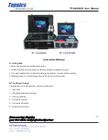
EX: DPYCYSLA - 1.5        MPYC - 4

Core                     Cable                                                              Core                    Cable

Type                 Area          Diameter                                          Type                 Area          Diameter

TTYCSLA-4

MPYC-4

TPYCY 

The following reference table lists gives the measurements of JIS cables commonly used with Furuno products:

Cables listed in the manual are usually shown as Japanese Industrial Standard (JIS). Use the following guide to locate an 
equivalent cable locally.

JIS cable names may have up to 6 alphabetical characters, followed by a dash and a numerical value (example: DPYC-2.5). 
For core types  D and T, the numerical designation indicates the 

cross-sectional Area (mm

2

)

 of the core wire(s) in the cable.  

For core types M and TT, the numerical designation indicates the 

number of core wires 

in the cable.

1. Core Type 

2.  Insulation Type  

3. Sheath Type

D  

Double core power line

 P 

Ethylene Propylene Rubber 

PVC (Vinyl)


Triple core power line

Multi core

TT

 Twisted pair communications (1Q=quad cable)

4. Armor Type 

5.  Sheath Type 


6. Shielding Type

Steel

 Y 

Anticorrosive vinyl sheath 

SLA


      -SLA


DPYCY 

Diameter

Diameter

DPYC-1.5 1.5mm

2

 1.56mm  11.7mm

DPYC-2.5 2.5mm

2

 2.01mm  12.8mm

DPYC-4 4.0mm

2

 2.55mm  13.9mm

DPYC-6 6.0mm

3.12mm 15.2mm 

DPYC-10 10.0mm

2

 4.05mm 

17.1mm

DPYC-16 16.0mm

2

 5.10mm 

19.4mm

DPYCY-1.5 1.5mm

1.56mm 13.7mm 

DPYCY-2.5 2.5mm

2

 2.01mm  14.8mm

DPYCY-4 4.0mm

2

 2.55mm  15.9mm

DPYCYSLA-1.5 1.5mm

2

 1.56mm  11.9mm

DPYCYSLA-2.5 2.5mm

2

 2.01mm  13.0mm

MPYC-2 1.0mm

2

 1.29mm  10.0mm

MPYC-4 1.0mm

2

 1.29mm  11.2mm

MPYC-7 1.0mm

2

 1.29mm  13.2mm

MPYCY-12 1.0mm

2

 1.29mm  19.0mm

MPYCY-19 1.0mm

2

 1.29mm  22.0mm

TPYCY-1.5 1.5mm

2

 1.56mm  14.5mm

TPYCY-2.5 2.5mm

2

 2.01mm  15.5mm

TPYCY-4 4.0mm

2

 2.55mm  16.9mm

TPYCYSLA-1.5 1.5mm

2

 1.56mm  13.9mm

TTYC-7SLA 0.75mm

2

 1.11mm 

20.8mm

TTYCSLA-1 0.75mm

2

 1.11mm 

9.4mm

TTYCSLA-1Q 0.75mm

2

 1.11mm 

10.8mm

TTYCSLA-4 0.75mm

2

 1.11mm 

15.7mm

TTYCY-4SLA 0.75mm

2

 1.11mm 

19.5mm

TTYCYSLA-1 0.75mm

2

 1.11mm 

11.2mm

TTYCYSLA-4 0.75mm

2

 1.11mm 

17.9mm

Designation type

Core Area (mm

2

)

Designation type

# of cores

1    2    3    4    5        6                                                1    2    3    4

All cores in one shield, 
plastic tape w/aluminum tape

Individually shielded cores, 
plastic tape w/aluminum tape

Summary of Contents for DFF1-UHD

Page 1: ...NETWORK FISH FINDER DFF1 UHD OPERATOR S MANUAL www furuno com Model...

Page 2: ......

Page 3: ...product according to local regulations for the disposal of industrial waste For disposal in the USA see the homepage of the Electronics Industries Alliance http www eiae org for the correct method of...

Page 4: ...tall or operate the equipment WARNING WARNING Do not open the equipment Only qualified personnel should work inside the equipment Do not disassemble or modify the equipment Fire electrical shock or se...

Page 5: ...stances shown below to prevent interference to a magnetic compass WARNING WARNING Do not open the equipment Only qualified personnel should work inside the equipment Turn off the power before beginnin...

Page 6: ...sensor T 02MSB T 03MSB 5 2 WIRING 6 2 1 Wiring Outline 6 2 2 Transducer Cable Cable for External KP option 7 2 2 1 How to process the cables 7 2 2 2 How to connect the transducer cable 9 2 2 3 How to...

Page 7: ...y for enhanced detection performance Fish size shown for depths up to 200 m and bottom discrimination Echoes are shown in high ultra definition thus echoes are displayed differently from those present...

Page 8: ...1 50 60 Hz NETWORK FISH FINDER DFF1 UHD 12 24 VDC Transducer Rectifier PR 62 Speed Temperature Sensor ST 02MSB ST 02PSB Temperature Sensor T 02MTB T 02MSB T 03MSB NavNet Equipment TZT9 14 BB B265LH o...

Page 9: ...31 1 kW plastic housing tank mount Thru hull pipe TFB 7000 000 022 532 Tank T 711 000 022 539 Cable Assembly MOD Z072 020 001 167 880 10 2 m for HUB 101 Cable Assembly MOD Z072 100 001 167 900 10 10 m...

Page 10: ...tilated Mount the unit where shock and vibration are minimal Keep the unit away from electromagnetic field generating equipment such as motors and gen erators Leave slack in cables for maintenance and...

Page 11: ...lar However the sensor must not be located where it may be damaged in dry docking operations Select a place apart from equipment generating heat Select a place in the forward direction viewing from th...

Page 12: ...T 02MTB Fix the cable at a convenient location with cable clamp When the cable is led in through the transom board make a hole of approx 17 mm in diameter to pass the connector After passing the cable...

Page 13: ...ide Sensor Holder T 02MSB T 03MSB Mounting procedure 1 Drill a hole of 21 mm in diameter in the mounting location 2 Pass the sensor cable through the hole 3 Pass gasket washer and locknut onto cable i...

Page 14: ...ake the length of the wire as short as possible For FRP vessels install a ground plate that mea sures about 20 cm by 30 cm on the outside of the hull bottom and connect the ground wire there DFF1 UHD...

Page 15: ...he transducer cable can be removed if it interferes with treatment of the cable How to process the transducer cable CM265LH B265LH Name Type Code No Qty Upset UI Screw B M4 20 000 163 756 10 2 Super G...

Page 16: ...to each core 2 Remove the armor 170 mm and cut off the vinyl sheath 90 mm 3 Remove 5 mm of the vinyl sheath from the cores then connect each crimp on lug attached at step 2 as shown below 4 Wrap the...

Page 17: ...xternal KP go to section 2 2 3 1 Open the cover Grasp the cover at two sides spread the cover slightly and lift 2 Loosen five screws to remove the shield cover 3 Detach the two WAGO connectors TB3 TB4...

Page 18: ...following the instructions in the figure below and the intercon nection diagram 8 Attach the WAGO connectors 9 Refasten the clamp fixing plate referring to the table below for how to orient the plate...

Page 19: ...g to steps 1 3 in section 2 2 2 2 Unfasten the lock nut of the inside the unit to detach the super gland 3 Unfasten two screws to remove the clamp fixing plate 4 Unfasten two screws securing the clamp...

Page 20: ...erial inside the unit 7 Using the two screws removed at step 5 fasten the upper two holes of the supplied rainproof ing panel Nut material Rainproofing panel Clamp Clamp fixing plate Rainproofing pane...

Page 21: ...2 0 N m 9 Set the nut material removed at step 6 inside the unit align its two protrusions with the lower holes on the rainproofing panel Use the remaining two screws removed at step 5 to fasten the l...

Page 22: ...per gland of the cable for the external KP unfasten the lock nut from the super gland then pass the cable through the super gland See page 8 for how to treat the cable end After passing the cable for...

Page 23: ...and connect the cable to J12 on the PWRTX board Be sure the cable does not contact TB4 Note For cable MPYC 2 tape the vinyl sheath of the cable approx 6 to 7 turns where it lies in the cable clamp and...

Page 24: ...ING 16 14 Attach the supplied EMI core GRFC 10 to the cable for the external KP approx 100 mm from the super gland 15 Attach the shield cover and close the outer cover Super gland for ext KP EMI core...

Page 25: ...he LAN connector then remove the sealing insert and clamping claw 2 Detach the sealing insert from the clamping claw as shown below Sealing nut Clamping claw Insert seal Sealing insert Super gland Sea...

Page 26: ...and clamping claw into the sealing nut then tighten the nut 5 Tighten the sealing nut to fasten the LAN cable The clearance between the lock nut and the sealing nut shall be 3 mm The torque for the s...

Page 27: ...h 2 referring to the table below ON Use IP address assigned by DHCP 2 IP address no OFF Set the 1 switch to OFF to set IP address See the table on the next page for IP address assignment 3 Restore def...

Page 28: ...LED on the cover of the DFF1 UHD lights or blinks according to equipment state as described in the table below LED state and meaning 2 Host name IP address OFF ES092002 172 031 092 002 ON ES092003 172...

Page 29: ...h Cleaning the network fish finder s cabinet Dust or dirt on the cabinet may be removed with a dry cloth Do not use chemical based cleaners to clean the cabinet they can remove markings and damage the...

Page 30: ...the NavNet series device You can restore all default settings or restore those other than transducer and LAN This procedure should only be performed by a suitably qualified FURUNO technician 1 Disconn...

Page 31: ...Type 5 Sheath Type 6 Shielding Type C Steel Y Anticorrosive vinyl sheath SLA SLA DPYCY Diameter Diameter DPYC 1 5 1 5mm2 1 56mm 11 7mm DPYC 2 5 2 5mm2 2 01mm 12 8mm DPYC 4 4 0mm2 2 55mm 13 9mm DPYC 6...

Page 32: ...2403 5 2403 10 1621 40 476 100 222 400 58 1200 34 2 INTERFACE 2 1 I O port Network 1 port Temp speed sensor 1 port External KP 1 port external KP kit option 2 2 Network method Ethernet 10Base T 100Ba...

Page 33: ...W 5X20 SUS304 000 162 608 10 4 LAN LAN CABLE ASSEMBLY MOD Z072 050 000 167 176 10 1 MJ CABLE ASSEMBLY MJ A3SPF0013 035C 5A 000 157 939 10 1 DOCUMENT OPERATOR S MANUAL OM 20400 000 177 244 1 1 CODE NUM...

Page 34: ...7 Dec 2012 Y NISHIYAMA...

Page 35: ...IN DRAIN MJ A3SPF GRN BLK WHT 5A 1 2 3 5 6 PR 62 RECTIFIER MJ A3SPF0013 035C 3 5m 12 24VDC GND IV 2sq 1 TEMP SPEED SENSOR ST 02MSB PSB T 02MTB MSB T 03MSB IV 2sq 1 2 10m 2 8 8 RJ45 RJ45 ETHERNET HUB H...

Page 36: ...cient Otherwise the invoice with serial number name and stamp of the dealer and date of purchase is shown For the Onboard Warranty your FURUNO certified dealer will take care of all registrations 5 Wa...

Page 37: ...or its authorized dealer at the time of request for warranty service This warranty is valid for installation of products manufactured by Furuno Electric Co hereafter FURUNO Any purchases from brick a...

Page 38: ......

Page 39: ......

Page 40: ...Dealer Printed in Japan Elemental Chlorine Free The paper used in this manual is elemental chlorine free 9 52 Ashihara cho Nishinomiya 662 8580 JAPAN All rights reserved Pub No OME 20400 B DAMI DFF1...

Reviews: