

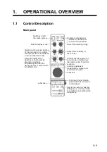


2. SONAR MODE
2-4
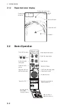
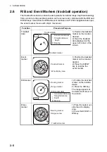
2.5
Setting the Tilt Angle
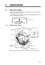
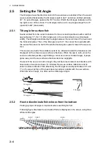
The tilt angle shows the direction to which the sound wave is emitted. When the sound
wave is emitted horizontally, the tilt angle is said to be 0° and when emitted vertically,
90°. To set a tilt angle, operate the TILT control. Watch the tilt angle indication at the
top right corner of the screen. The tilt angle can be set in one-degree steps from +5°
(upward) to 90° (downward).
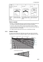
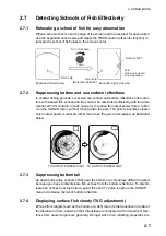
2.5.1
Tilt angle for surface fish
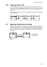
Sound emitted from the sonar transducer forms an oval-shaped beam with a width of
approximately 11° (for 113 kHz transducer) in the vertical direction (vertical beam
width). The tilt angle is indicated by the angle between the center line of the beam and
the horizontal plane. Then, if the tilt angle is set to 0°, the center line is parallel with
the sea surface and one half of the emitted sound goes upward, toward the sea sur-
face.
This causes one half of the emitted sound to be reflected toward the transducer and
displayed on the screen as sea surface reflections. When the sea is calm, since the
sound is reflected just like a light hitting a mirror at a narrow incident angle, it propa-
gates away and the sea surface reflections become negligible
However if the sea is not calm enough, they will become dominant and interfere with
observation of wanted echoes. To minimize these sea surface reflections and to
search surface schools of fish effectively, the tilt angle is usually set between 5° and
7° so the upper portion of the beam becomes almost parallel with the sea surface.
When the sea is rough, it is often set to a little larger angle.
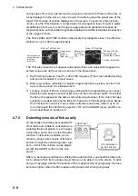
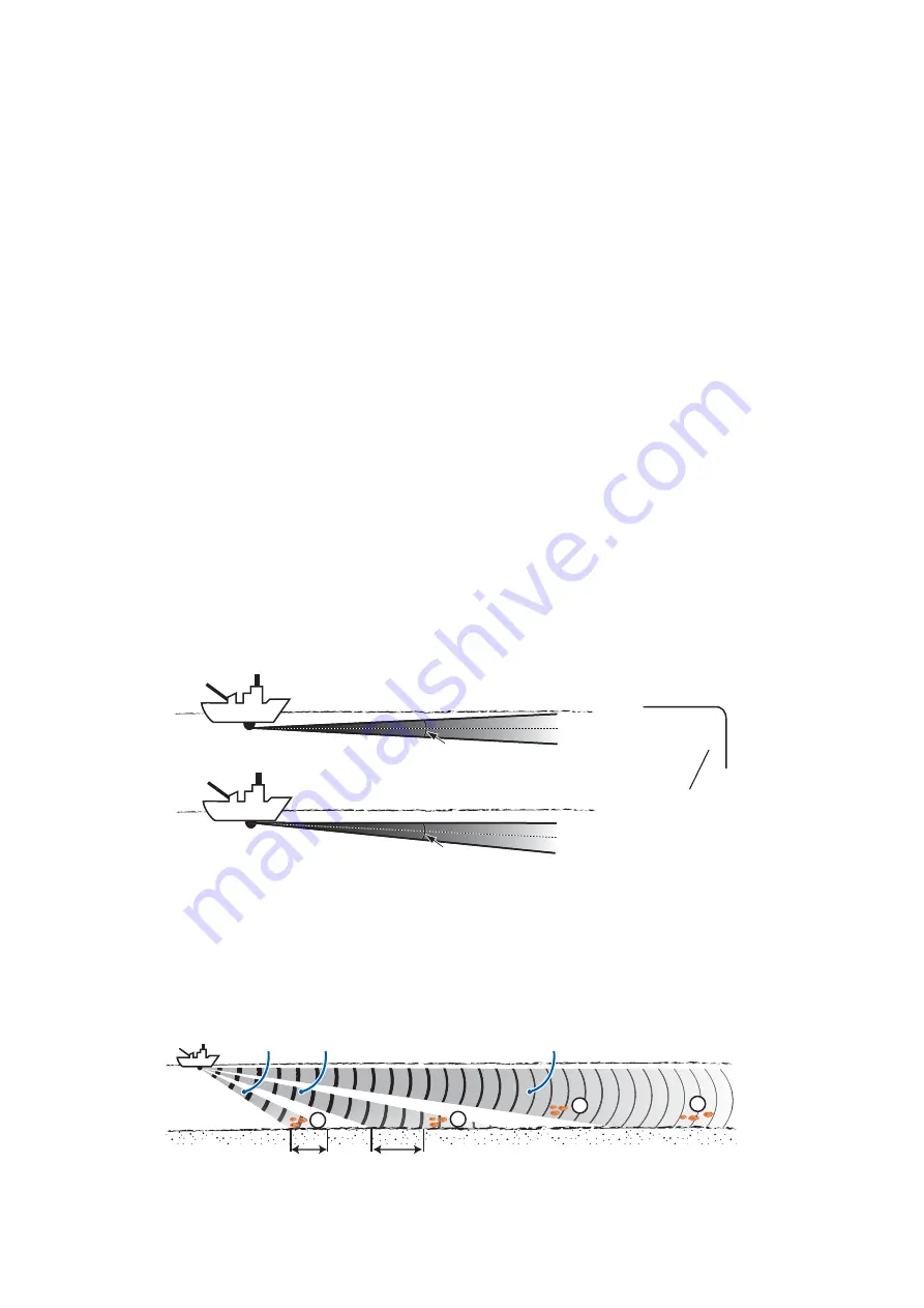
2.5.2
How to discriminate fish echoes from the bottom
Finding a proper tilt angle is important when searching for fish.
Following figure illustrates how schools of fish are displayed on the screen using three
different tilt angles.
11°
11°
Tilt angle 0°
Tilt angle 5° - 7°
R400
T 15
Tilt angle
CASE 1
㪚㪘㪪㪜㩷㪉
CASE 3
a
a
a
b
Summary of Contents for CH-37BB
Page 1: ...COLOR SECTOR SCANNING SONAR CH 37BB OPERATOR S MANUAL www furuno com Model ...
Page 10: ...SYSTEM CONFIGURATION viii This page is intentionally left blank ...
Page 40: ...3 VERTICAL FAN MODE 3 12 This page is intentionally left blank ...
Page 44: ...4 3D MODE 4 4 This page is intentionally left blank ...
Page 48: ...5 PRESENTATION MODE 5 4 This page is intentionally left blank ...
Page 52: ...6 CUSTOM MODE KEYS 6 4 This page is intentionally left blank ...
Page 58: ...7 SYSTEM MENU 7 6 This page is intentionally left blank ...
Page 66: ...8 MAINTENANCE 8 8 This page is intentionally left blank ...


