background image


15 

VNS 102V2

11/2009


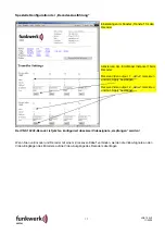
IP-Adresse wie gewünscht einstellen  
(z.B. 

192.168.128.10

 für den Encoder 

und 

192.168.128.11 

für den Decoder

)


anschließend mit „Store & apply“ im 
VNS 102V2 speichern. 

Hinweis: 
Die Verbindung zwischen Explorer und 
VNS 102V2 ist bei Änderung der IP-
Adresse unterbrochen, eine erneute 
Verbindung muss mit der neu 
eingestellten IP-Adresse über den 
Explorer erfolgen. 
 
Achtung! 
Die IP-Adresse des Encoders und des 
Decoders muss unterschiedlich 
eingestellt werden! 

(Aber miteinander korrespondierend!) 


Spezielle Konfiguration der „Encoder-Ausführung“ 


Einstellungen im Fenster „VideoCodecs“ für 
den Encoder  
 
Aktivierung der Video-Inputs beim Encoder: 
 
Instance 1: „

aktive

“ markieren und mit „Apply“ 

bestätigen. 
 
Instance 2: „

aktive

“ markieren und mit „Apply“ 

bestätigen. 
 

Summary of Contents for plettac VNS 102V2

Page 1: ...c GmbH Würzburger Str 150 D 90766 Fürth Tel 0911 75884 0 43522 941 96 00 Fax 0911 75884 100 Änderungen vorbehalten Subject to change without notice 11 2009 D Bedienungs Montageanleitung GB Operation Installation Manual VNS 102V2 ...

Page 2: ...Erstinbetriebnahme Konfiguration 12 Inbetriebnahme und Konfiguration des VNS 102V2 12 Technische Daten 18 Maßbild VNS 102V2 18 GB English General description 21 Maintenance 21 Troubleshooting 21 Delivery scope 22 Disposal 22 Pin assignment VNS 102V2 23 Voltage supply of the VNS 102V2 24 LAN interface 25 Serial RS485 interface 26 Audio 27 Digital I O 28 Accessories for the VNS 102V2 29 Commissionin...

Page 3: ...geschäden wird keine Haftung übernommen Der VNS 102V2 darf nur bestimmungsgemäß eingesetzt und nicht außerhalb seiner spezifizierten Betriebs und Umgebungsbedingungen betrieben werden Der VNS 102V2 darf nur von autorisiertem Fachpersonal montiert werden Geltende Sicherheitsbestimmungen und Unfallverhütungsvorschriften sind zu beachten Vor Montage oder Servicearbeiten Betriebsspannung abschalten Be...

Page 4: ... Die eingesetzte Lösung lässt dem Kunden des Weiteren die Wahlmöglichkeit einer frei skalierbaren Mindest Bildqualität bei variabler Bildrate zur Minimierung der Netzlast Hinweis Diese Bedienungsanleitung ist nur für den Anschluss des VNS 102V2 und die ersten Schritte der Inbetriebnahme anzuwenden Details Spezielle Einstellungen und Funktionshinweise sind der Technischen Dokumentation 43522942 91 ...

Page 5: ...c 19 Einbaukassette Best Nr 943522190600 CD mit ausführlicher Dokumentation und Streaming Plugin SW 2 Jumper Bedienungs und Montageanleitung Best Nr 435229419600 Entsorgung Entsorgen Sie das Gerät entsprechend den geltenden gesetzlichen Vorschriften ...

Page 6: ...VNS 102V2 11 2009 6 Steckerbelegungen VNS 102V2 RJ 45 I O RJ 45 Audio 4 poliger DIP SWITCH PIN 1 2 3 4 RJ 45 Audio RJ 45 I O ...

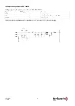
Page 7: ...ungsversorgung erfolgt über den Powerstecker auf der Rückseite des VNS 102V2 Signal WAGO Stecker Pin Beschreibung GND 1 Pol Ground UB 2 Pol Power min 9 5 bis max 32 VDC FRAME 3 Chassis Ground Empfohlenes Netzteil für Einbau in 19 Baugruppenträger TM11 siehe Zubehör ...

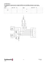
Page 8: ...tspricht dem Standard IEEE802 1 mit 10 100Mbit autosense über Cat 5 Kabel 10 100BaseT Als LAN Anschluss steht ein RJ45 Stecker an der Frontseite des VNS 102V2 mit der Bezeichnung LAN zur Verfügung Signal RJ45 LAN Pin Signal RJ45 LAN Pin TX 1 TX 2 RX 3 4 5 RX 6 7 8 ...

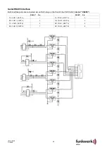
Page 9: ...chnittstellenports erfolgt über einen RJ45 Stecker an der Frontseite des VNS 102V2 mit der Bezeichnung RS485 RS485 Pin RS485 Pin TX COM 1 UART A 1 TX COM 1 UART A 2 RX COM 1 UART A 3 TX COM 2 UART B 4 TX COM 2 UART B 5 RX COM 1 UART A 6 RX COM 2 UART B 7 RX COM 2 UART B 8 ...

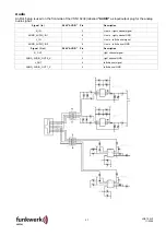
Page 10: ...ndet Signal In RJ45 AUDIO Pin Beschreibung R_IN 3 Line In rechter Kanal Signal AGND_AUDIO_IN1 6 Line In rechter Kanal GND L_IN 7 Line In linker Kanal Signal AGND_AUDIO_IN2 8 Line In linker Kanal GND Signal Out RJ45 AUDIO Pin Beschreibung R_OUT 1 rechter Kanal Signal AGND_AUDIO_OUT2_X 2 rechter Kanal GND L_OUT 4 linker Kanal Signal AGND_AUDIO_OUT1_X 5 linker Kanal GND ...

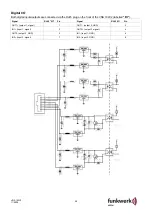
Page 11: ...ber den RJ45 Stecker an der Frontseite des VNS 102V2 mit der Bezeichnung I O Signal RJ45 I O Pin Signal RJ45 I O Pin OUT1 Ausgang 1 Signal 1 OUT1 Ausgang 2 GND 2 IN1 Eingang 1 Signal 3 OUT2 Ausgang 2 Signal 4 OUT2 Ausgang 2 GND 5 IN1 Eingang 1 GND 6 IN2 Eingang 2 Signal 7 IN2 Eingang 2 GND 8 ...

Page 12: ...bracht entfernt werden da sonst bei jedem weiteren Hochlauf jedesmal der Auslieferzustand hergestellt würde Notwendiges Zubehör zur Erstinbetriebnahme Konfiguration Gekreuztes LAN Kabel Cross Over zum PC oder HUB 3 LAN Kabel Geeignete Stromversorgung Videoquelle Monitor Videokabel Inbetriebnahme und Konfiguration des VNS 102V2 Hinweis Die nachfolgende Konfiguration erlaubt eine Übertragung von 2 u...

Page 13: ...ist nur dann möglich wenn die Netzwerkeinstellung des PC mit der Klasse der IP Adresse und der verwendeten Subnetzmask des VNS 102V2 übereinstimmt Bei den weiteren Einstellungen wird davon ausgegangen dass ein PC mit Windows XP verwendet wird Anpassung der Netzwerkkonfiguration des verwendeten PC s an den VNS 102V2 Hinweis Bevor Sie die Netzwerkeinstellungen Ihres PC s verändern notieren Sie sich ...

Page 14: ...ellen Hinweis Falls sich nach dem Ändern von IP Adressen mit dem Browser keine Verbindung mehr herstellen läßt kann ein Löschen der ARP Einträge durch Eingabe von arp d im DOS Fenster des PC s weiterhelfen Internetexplorer öffnen und die lokale Adresse 192 168 128 2 eingeben die Homepage des VNS 102V2 wird nun dargestellt Login wird aktiviert wenn Sie eine beliebige Config Page auswählen Login Use...

Page 15: ...rochen eine erneute Verbindung muss mit der neu eingestellten IP Adresse über den Explorer erfolgen Achtung Die IP Adresse des Encoders und des Decoders muss unterschiedlich eingestellt werden Aber miteinander korrespondierend Spezielle Konfiguration der Encoder Ausführung Einstellungen im Fenster VideoCodecs für den Encoder Aktivierung der Video Inputs beim Encoder Instance 1 aktive markieren und...

Page 16: ...ende Instanzen beim Encoder Instance 1 aktive markieren und mit Apply bestätigen Instance 2 aktive markieren und mit Apply bestätigen Der VNS 102V2 Encoder ist jetzt so konfiguriert dass zwei Videosignale gestreamt werden wenn an beiden Videoeingängen ein normgerechtes Videosignal anliegt ...

Page 17: ... output 1 aktive markieren und mit Apply bestätigen Receive Video output 2 aktive markieren und mit Apply bestätigen Der VNS 102V2 Decoder ist jetzt so konfiguriert dass zwei Videosignale empfangen werden Wenn Sie nun Encoder und Decoder mit einem Crossover Kabel verbinden werden die Video Signale an den Video Eingängen des Encoders auf die Video Ausgänge des Decoders übertragen ...

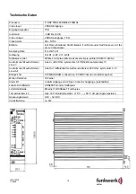
Page 18: ...e profile ISO IEC 14496 2 Audio mono Pseudo Stereo Line In Line In 600 Ohm symmetrisch 8 16 32kHz sample rate 1V Audio mono Pseudo Stereo Line Out Line Out differential mono Pseudo Stereo 600 Ohm symmetrisch 1V Bildspeicher 128 MB SDRAM on Board ca 83 MB Video Audio Alarmspeicher Motion Detection 16 Felder Alarm I O 2 Alarmeingänge und 2 Open Collector Ausgänge potentialfrei serielle Schnittstelle...

Page 19: ......
Page 20: ...device We will not assume any liability for consequential damage The VNS 102V2 may only be used according to purpose and not operated outside of its specified operating and ambient conditions Only authorised experts may assemble the VNS 102V2 Observe the valid safety and accident prevention regulations Shut off the operating voltage prior to installation or service work Only original parts may be ...

Page 21: ...oadband LAN and ISDN up to GMS The applied solution also allows the customer to select a freely scalable minimum image quality with variable frame rate to minimise the system load Notice Only use this operating manual for the connection of the VNS 102V2 and its initial commissioning Details special settings and function notices are included in the Technical Documentation 43522942 91 For informatio...

Page 22: ...V2 codec 19 built in cassette Order no 943522190600 CD with detailed documentation and streaming plugin SW 2 jumpers Operating and installation manual Order no 435229419600 Disposal Dispose of the device in line with the valid legal regulations ...

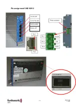
Page 23: ...23 VNS 102V2 11 2009 Pin assignment VNS 102V2 4 Pin DIP SWITCH PIN 1 2 3 4 RJ 45 Audio RJ 45 I O ...

Page 24: ...age supply via the power plug on the rear of the VNS 102V2 Signal WAGO plug pin Description GND 1 pole ground UB 2 pole power min 9 5 up to max 32 VDC FRAME 3 Chassis ground Recommended power supply unit for installation into 19 sub rack TM11 see accessories ...

Page 25: ...e corresponds to the standard IEEE802 1 with 10 100Mbit autosense via cat 5 cable 10 100BaseT An RJ45 connector is located on the front of the VNS 102V2 for LAN connection labelled LAN Signal RJ45 LAN Pin Signal RJ45 LAN Pin TX 1 TX 2 RX 3 4 5 RX 6 7 8 ...

Page 26: ...terface ports are connected via an RJ45 plug on the front of the VNS 102V2 labelled RS485 RS485 Pin RS485 Pin TX COM 1 UART A 1 TX COM 1 UART A 2 RX COM 1 UART A 3 TX COM 2 UART B 4 TX COM 2 UART B 5 RX COM 1 UART A 6 RX COM 2 UART B 7 RX COM 2 UART B 8 ...

Page 27: ...In RJ45 AUDIO Pin Description R_IN 3 Line In right channel signal AGND_AUDIO_IN1 6 Line In right channel GND L_IN 7 Line In left channel signal AGND_AUDIO_IN2 8 Line In left channel GND Signal Out RJ45 AUDIO Pin Description R_OUT 1 right channel signal AGND_AUDIO_OUT2_X 2 right channel GND L_OUT 4 left channel signal AGND_AUDIO_OUT1_X 5 left channel GND ...

Page 28: ...ected via the RJ45 plug on the front of the VNS 102V2 labelled I O Signal RJ45 I O Pin Signal RJ45 I O Pin OUT1 output 1 signal 1 OUT1 output 2 GND 2 IN1 input 1 signal 3 OUT2 output 2 signal 4 OUT2 output 2 GND 5 IN1 input 1 GND 6 IN2 input 2 signal 7 IN2 input 2 GND 8 ...

Page 29: ...pply Video source Monitor Video cable Commissioning and configuring the VNS 102V2 Notice The following configuration allows the transmission of 2 different video signals via LAN from a VNS 102V2 encoder to a VNS 102V2 decoder Here the video quality is 2CIF with 2Mbit s bandwidth each Here the signal on video 1 from the encoder is transmitted to video 2 of the decoder and video 2 from the encoder t...

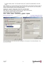
Page 30: ... with Windows XP Adapting the network configuration of the PC to the VNS 102V2 Notice Before you change the network settings of your PC please note them down You can locate the network settings of the PC as follows Press the following buttons in the stated sequence START Æ Settings Æ Network Æ LAN connection Æ Properties Æ Properties Select the Internet protocol TCP IP E g enter the IP address 192...

Page 31: ... VNS 102V2 decoder Notice If it is no longer possible to establish a connection with the browser after changing IP addresses deleting the ARP entries by entering arp d in the DOS window may be helpful Open the Internet Explorer and enter the local address 192 168 128 2 Now you will see the homepage of the VNS 102V2 Login is activated when you select any config page Login User plettac Password catt...

Page 32: ...NS 102V2 is interrupted a new connection must be established via the Explorer with the newly set IP address Attention The IP address of the encoder and the decoder must be different But corresponding with each other Special configuration of the encoder model Settings in the window VideoCodecs for the encoder Activation of the video inputs on the encoder Instance 1 Mark active and confirm with appl...

Page 33: ...n of the send instances on the encoder Instance 1 Mark active and confirm with apply Instance 2 Mark active and confirm with apply Now the VNS 102V2 encoder is configured in such a way that two video signals are streamed if a standard video signal is applied to both video inputs ...

Page 34: ...er Receive video output 1 Mark active and confirm with apply Receive video output 2 Mark active and confirm with apply Now the VNS 102V2 decoder is configured to receive two video signals If you now connect the encoder and the decoder with a crossover cable the video signals on the video inputs of the encoder are transmitted to the video outputs of the decoder ...

Page 35: ...mple profile ISO IEC 14496 2 Audio mono pseudo stereo line in Line in 600 Ohm symmetric 8 16 32kHz sample rate 1V Audio mono pseudo stereo line out Line out differential mono pseudo stereo 600 Ohm symmetric 1V Image memory 128 MB SDRAM on board ca 83 MB video audio alarm memory Motion detection 16 fields Alarm I O 2 alarm inputs and 2 open collector outputs potential free Serial interface 2 RS485 ...

Reviews: