Fulling Motor FD430 User Manual Download Page 9


User’s Manual for FD430 Digital 2-Phase Stepper Driver


User’s Manual for FD430 Digital 2-Phase Stepper Driver 


15                                                                                                                                                                                                                                                                                                                                                                                              16 

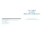
terminals  of    the  same  phase  of  the  driver(A+,A-  is  one  phase,  B+,B-  is  another 
phase).  57HS22  motor  lead  definition,  Series  and  Parallel  Connections  method  is 
shown below.   


3


FD430 driver can only drive 2-phase hybrid step motors, which cannot drive 3-phase 
and 5-phase stepping motor. 

4


The  method  of  judging  whether  the  stepping  motor  is  connected  in  series  or  in 
parallel is correct, When the  driver is  not connected, directly rotate the  motor shaft 
by  hand, If it can rotate easily and evenly, then the  wiring  method is correct; If the 
resistance is large and uneven rotation with a certain sound, then the wiring method 
is incorrect. 


. Protection Functions 

1


Short Circuit Protection / Over-current Protection


Over-current protection will be activated when continuous current exceeds the limit 

current value or in case of short circuit between motor coils or between motor coil and 

ground, and RED LED will turn on once within each periodic time (3 s). Reset the driver 

by repowering it to make it function properly after removing above problems. 

2


Over-voltage protection 

When power supply voltage exceeds 38VDC, protection will be activated and RED 

LED will turn on twice within each periodic time (3 s). Reset the driver by repowering it 

to make it function properly after removing above problems. 

3

Phase Error Protection


Motor power lines wrong & not connected will activate this protection. RED LED 

will turn on four times within each periodic time (3 s). Reset the driver by repowering it 

to make it function properly after removing above problems. 

Attention

since there is no protection against power leads (

) reversal, it is critical 

to make sure that power supply leads correctly connected to driver. Otherwise, the driver 

will be damaged instantly. 


. Frequently Asked Questions 

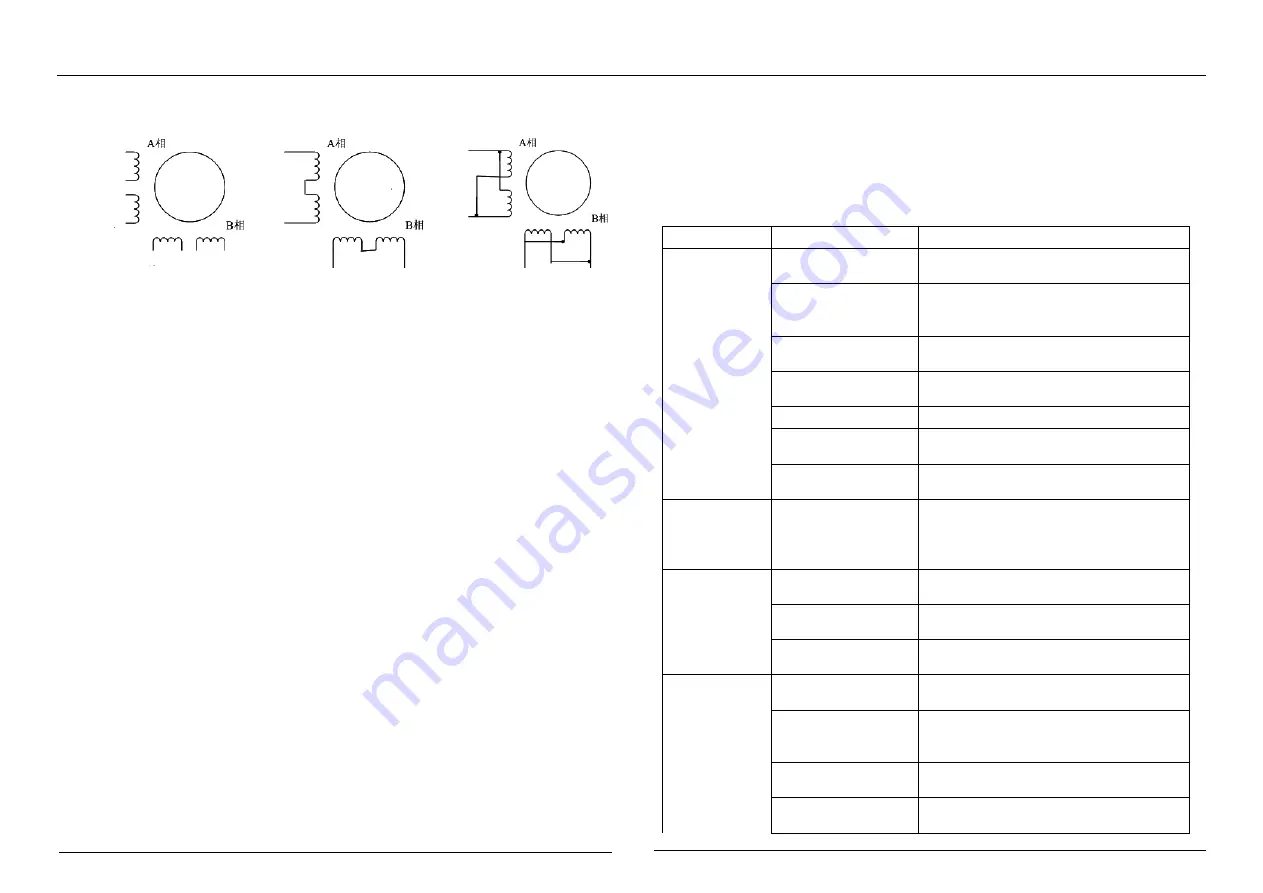
1. Problem Symptoms and Possible Causes 

Symptoms


Possible Problems


Solution


Motor is not 

rotating


No Power


Check the power supply circuit for normal 

power supply


The motor shaft 

strong, Control signal 

is too weak.


Control pulse signal is too weak, Signal 

current increased to 7~16mA


microstep resolution 

is too small


select the right microstep resolution 

setting


Current setting is too 

small


Select the right current setting


Drive is protected.


Power on again


Enable signal is low 

high.


Enable signal is high or not connected.


Does not respond to 

Input control signals


Not powered.


Motor 

rotating in the 

wrong 

direction


Motor phases may be 

connected in reverse


Exchanging the connection of two wires 

for a coil to the driver will reverse motion 

direction.


Alarm 

indicator is on


Wrong motor 

connection


Check connection


Power supply is too 

high or too low.


Check Power Supply


Motor or Driver is 

bad

Replace motor or driver


Inaccurate 

location


Control signal is 

disturbed


Eliminate interference


Shielded ground is 

not connected or 

disconnect


Reliable grounding.


Open winding of 

motor 

Check motor wire 

Micro-step resolution 

setting is wrong. 

select the right micro-step resolution 

setting 


Lead definition


Tandem


Parallel 

57HS22 

57HS22 

57HS22 

S45 

S45 

S45 

绿

S45 

S45 

S45 

S45 

S45 

Figure8 Tandem and Parallel connection 

Summary of Contents for FD430

Page 1: ...u City 213032 China Tel 86 519 85132957 Fax 86 519 85132956 Web site www fullingmotor com Email info fullingmotor com User s Manual For FD430 Digital 2 Phase Stepper Driver All Rights Reserved No reproduction Attention Please read this manual carefully before using the drive ...

Page 2: ... Introduction 错误 未定义书签 1 Interface Description 4 2 Control Signal Interface Circuit 5 3 Sequence Chart of Control Signals 5 4 Control Signal Mode Setting 6 5 Wiring Require 6 Ⅳ Selecting Microstep Resolution Driver Output Current and Parameter auto tuning 错误 未定义书签 1 Current Settings 6 2 Microstep Resolution Selection 6 3 Parameter atuo tuning function 7 Ⅴ Power Supply Selection 错误 未定义书签 Ⅵ Motor Op...

Page 3: ...ration technology Output current programmable from 0 1A to 3A Variable current control for less motor heating Micro step resolutions programmable range from 200 to 51200 steps rev Automatic idle current reduction in half Over voltage Under voltage over current protections 3 Applications It can be used in various kinds of small and medium sized equipment and machines such as engraving machines labe...

Page 4: ...two directions of motor rotation For reliable motion response DIR signal should be ahead of PUL signal by 2μs at least 4 5V 28Vdc when DIR HIGH 0 0 5V when DIR LOW Please note that rotation direction is also related to motor driver wiring match Exchanging the connection of two wires for a coil to the driver will reverse motion direction DIR ENA Enable signal This signal is used for enabling disabl...

Page 5: ...ngle ended common cathode or common anode control signals from the controller can also be accepted by this interface The input circuit has built in high speed opto coupler and can accept signals in the format of line driver open collector or PNP output Recommend use line driver control signals to increase noise immunity of the driver in interference environments In the following figures connection...

Page 6: ...r P2 with power on will cause extremely high back EMF voltage surge which may damage the driver 5 It is strictly forbidden to add lead to the terminal after adding tin otherwise the terminal may be damaged due to the increased contact resistance 6 Lug must not be exposed outside the terminal to prevent accidental short circuit and damage to the driver Ⅳ Driver Current Output Selecting Microstep Re...

Page 7: ... the driver setting current 4 If regulated supply is used the average current withdrawn from power supply is more than or equal to driver current 5 It is recommended to have two or three drives to share one power supply to reduce cost if the supply has enough capacity Ⅵ Motor option The FD430 can drive any 2 phase and 4 phase of 4 6 8 lead hybrid stepping motors which is suitable for 1 8 and 0 9 s...

Page 8: ...tion 6 lead motor high speed Mode the motors should also be run at only 100 of their rated current which is unipolar connection 8 lead motor Series Connections the motors should also be run at only 70 of their rated current which is unipolar connection 8 lead motor Parallel Connections the motors should also be run at only 140 of their rated current which is unipolar connection Note After the curr...

Page 9: ...LED will turn on four times within each periodic time 3 s Reset the driver by repowering it to make it function properly after removing above problems Attention since there is no protection against power leads reversal it is critical to make sure that power supply leads correctly connected to driver Otherwise the driver will be damaged instantly Ⅸ Frequently Asked Questions 1 Problem Symptoms and ...

Page 10: ...at is the relationship between the speed of the stepping motor and the pulse frequency Because of its unique structure the stepping motor is marked with the inherent step angle when it leaves the factor The step angle such as 0 9 degree 1 8 degree it means that the angle turned by each step of the half step work is 0 9 degree and the full step is 1 8 degree However in many precision control situat...

Page 11: ...g unauthorized modification or misuse or operation beyond the electrical specifications of the product and or operation beyond environmental specifications for the product And poor ambient heat dissipation 3 Obtaining Warranty Service If your product fail during the warranty period need to obtain a returned material authorization number before returning product for service Please include a written...

Reviews: