


User’s Manual for FD430 Digital 2-Phase Stepper Driver
User’s Manual for FD430 Digital 2-Phase Stepper Driver
17 18
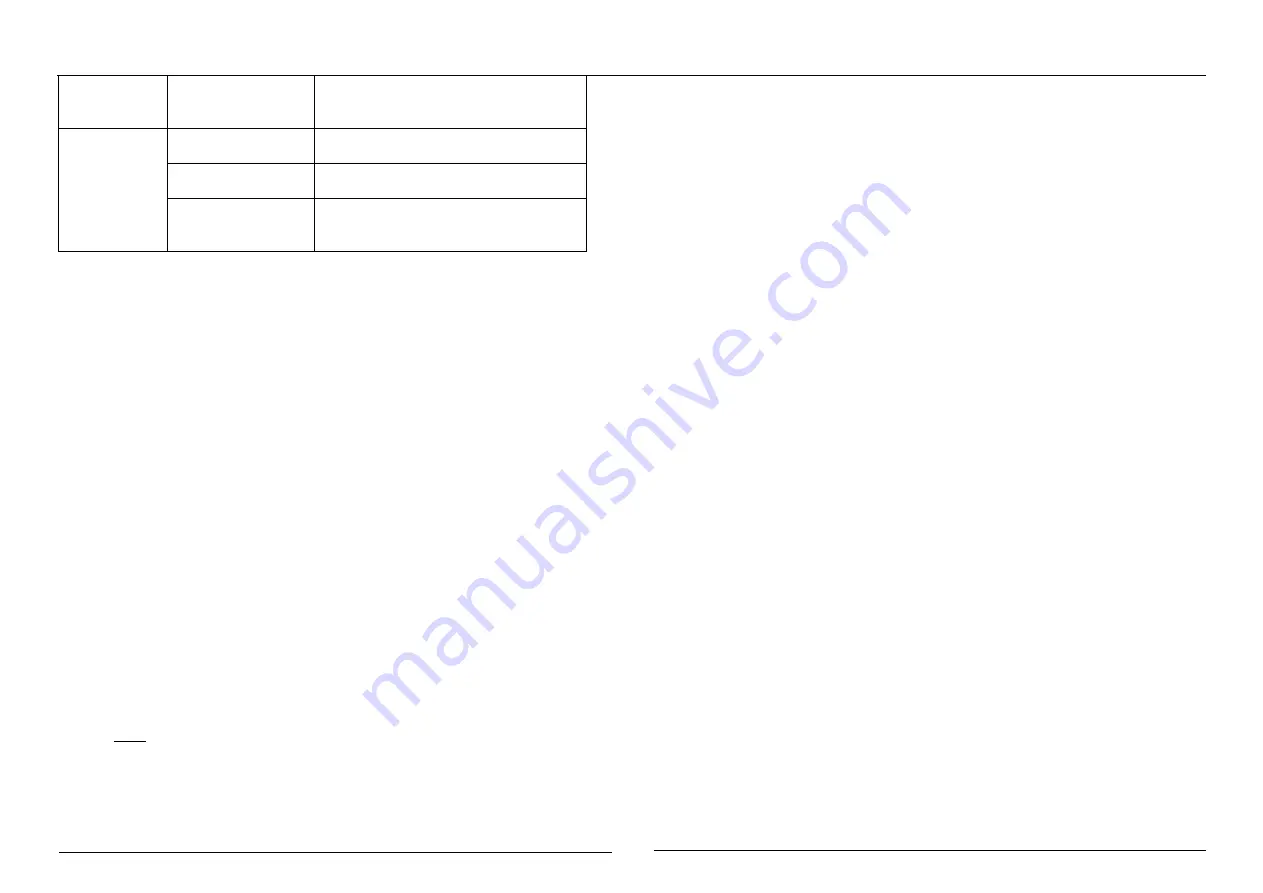
Current setting is too
small, losing steps
Choose another power supply with lager
power or increase the output current of
drive.
Motor stalls
during
acceleration
Acceleration is set
too high
Reduce the acceleration
Motor is undersized
for the application
Choose another motor with higher torque
Power supply voltage
too low or Current
setting is too small.
Choose another power supply with larger
power or increase the output current of
drive
2. Drive Frequently Asked Questions
1
)
What are Stepper Motor and Stepper Driver?
A stepper motor is a particular type of DC motor that can achieve very precise positioning
and/or speed control. When a discrete DC voltage is applied, the stepper motor rotates in
a particular angle called the step angle. Therefore calls Stepping motor which is
characterized by no cumulative error. Receive each a pulse of electric from controller, the
motor is driven at a fixed angle by the diver, So it is widely used in various open loop
control.
The stepping driver is a power amplifier that enables the stepping motor to run, It can
convert the pulse signal from the controller into the power signal of the stepping motor.
The speed of the motor is proportional to the pulse frequency, So the control pulse
frequency can be adjusted precisely speed, the number of control pulses can be accurately
positioned.
2
)
What is the drive resolution? What is the relationship between the speed of the
stepping motor and
the
pulse frequency?
Because of its unique structure, the stepping motor is marked with the inherent step
angle when it leaves the factor. The step angle such as 0.9 degree/1.8 degree, it means
that the angle turned by each step of the half-step work is 0.9 degree, and the full-step is
1.8 degree. However, in many precision control situations, the angle of the entire step is
too large, which affects the control accuracy and the vibration is too large. Therefore, it is
required to complete a motor’s inherent step angle via in many subdivision steps. This is
the so-called subdivision drive, the electronic device capable of this function is called a
micro-step resolution driver.
V
:
Motor Speed(r/s)
P
:
Pulse frequency(Hz)
Θe: Motor inherent step angle
m: Number of subdivisions(1 for full-step, 2 for half-step)
3
)
What are the benefits of subdivision driver?
●
Reduce the step angle of each step, improve the step uniformity, so the control accuracy
can be improved.
●
The method can make the rotor run smoothly, so this method can be considered as one
of the effective methods to reduce vibration at low speed.
●
Can effectively reduce torque ripple and increase output torque.
4
)
Why does my motor only turn in one direction?
●
The direction signal may be too weak, or the wiring polarity is wrong, or the signal
voltage is too high which lead to burn-out direction current limiting resistor.
●
The pulse mode does not match, The signal is in the pulse/direction, So the driver must
be set to this mode. If the signal is CW/CCW(double pulse mode), the driver must also be
in this mode, otherwise the motor will only run in one direction.
P*θe
360*m
V=


