


User’s Manual for FD430 Digital 2-Phase Stepper Driver
User’s Manual for FD430 Digital 2-Phase Stepper Driver
5 6
Weight
Approx. 0.090 Kg
3.
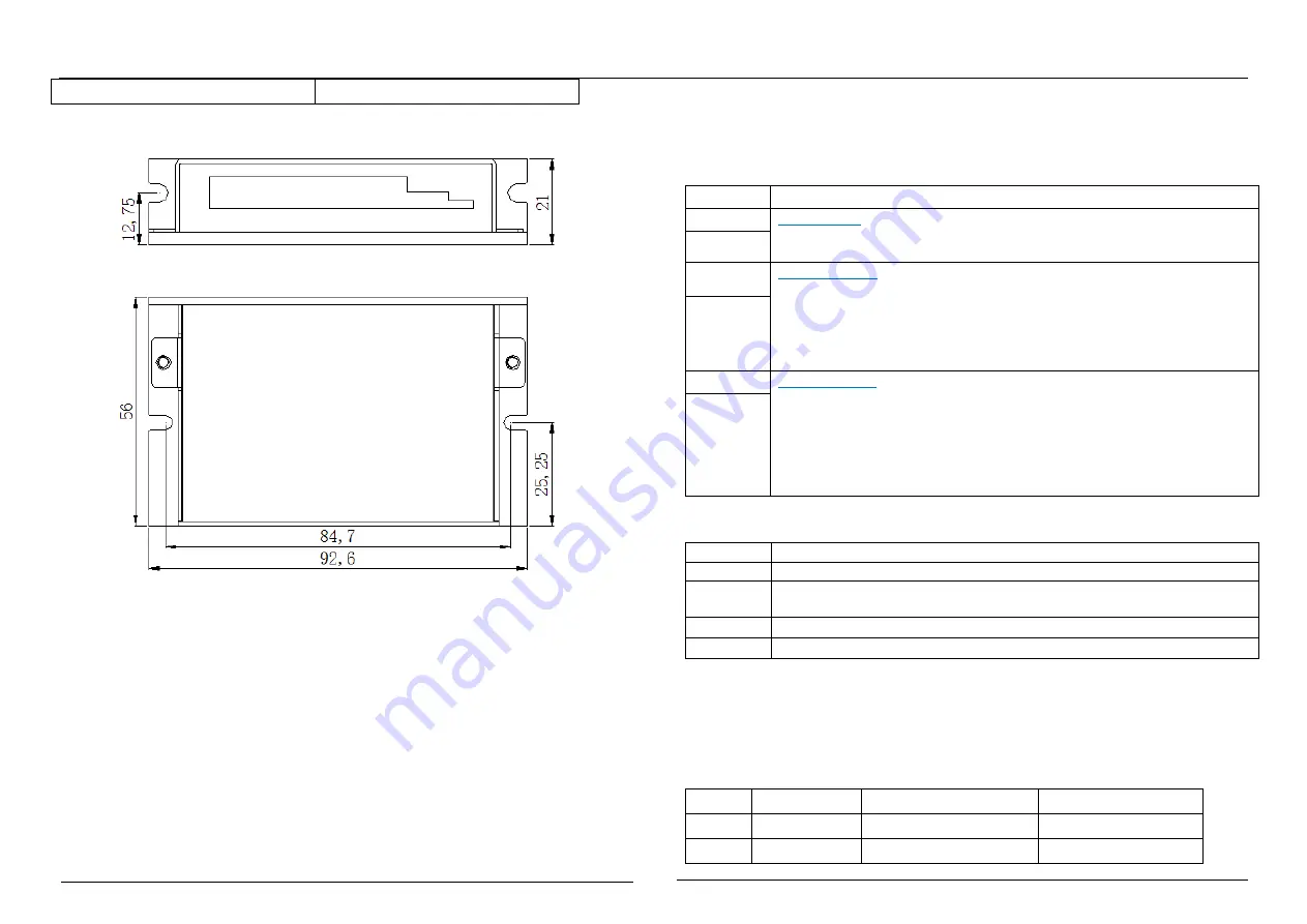
Mechanical Dimensions (unit: mm, 1 inch = 25.4 mm)
Figure 1: Mechanical dimensions
*Recommended to use side mounting for better heat dissipation, When designing
the installation size, pay attention to the terminal size and wiring.
4.
Elimination of Heat
1
)
Driver’s reliable working temperature should be <60
℃
, and motor working
temperature should be <80
℃
(176
℉
);
2
)
It is recommended to use automatic idle-current mode, namely current
automatically reduce to 50% when motor stops, so as to reduce driver heating and
motor heating;
3
)
It is recommended to mount the driver vertically to maximize heat sink area. Use
forced cooling method to cool the system if necessary, Ensure that the drives
operation in a reliable operating temperature range.
Ⅲ
. Pin Assignment and Description
1. Interface description
1
)
Control Signal Connector
Signal
Functions Details
PUL+
Pulse signal: This input represents pulse signal, each rising edge active,
4.5~28Vdc when PUL-HIGH, 0~0.5V when PUL-LOW, For reliable
response, pulse width should be longer than 1.5μs.
PUL-
DIR+
Direction signal: this signal has low/high voltage levels, representing two
directions of motor rotation; For reliable motion response, DIR signal
should be ahead of PUL signal by 2μs at least. 4.5V-28Vdc when
DIR-HIGH, 0-0.5V when DIR-LOW. Please note that rotation direction is
also related to motor-driver wiring match. Exchanging the connection of
two wires for a coil to the driver will reverse motion direction.
DIR-
ENA+
Enable signal:
This signal is used for enabling/disabling the driver. High
level for enabling the driver and low level for disabling the driver. When
ENA-HIGH is connected to 4.5V-28Vdc, ENA-LOW is connected to
0-0.5V (or Internal optical coupling is conducted), the driver will cut off
the current of each phase of the motor to make the motor in a free state,
step pulses are not responded at this time. Usually left
unconnected
(enabled)
.
ENA-
2
)
Power Connector Configurations
Signal
Functions Details
GND
Power Ground.
+Vdc
power supply, +12V~ +32Vdc Including voltage fluctuation and EMF
voltage, Recommended 24Vdc supply.
A+
、
A-
Motor coil A (leads A+ and A-)
B+
、
B-
Motor coil B (leads B+ and B-)
3
)
RS232/RS485 Communication Port
Special RS232 cable (Prohibition of charging plug) designed to setup
communication between the drive and PC-based configuration & tuning software
ProTuner. The PC software is used to configure the peak current, microstep, active level,
current loop parameters and the driver function, and so on.
Pin
Symbol
Name
Description
1
+5V
+5V power output
For external STU only
2
TxD
RS232 transmit


