background image

14 VIOM database

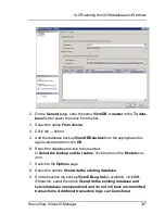
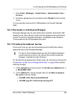
Stop the services

ServerView Virtual IO Manager Services

and

Server-

View Virtual IO DB Backup Services

:

1. Select

Start – [Settings] – Control Panel – Administrative Tools –

Services

.

2. Select the appropriate service and then select

Stop

from the context

menu.

Restrict the access to the VIOM database:

1. Start SQL Server Management Studio.

2. Connect with the SQL Server instance and select

Databases –

ViomDB

.

3. Select

Properties

from the context menu.

4. Select the

Options

page and, under

Restrict Access

, select the entry

RESTRICTED_USER

. Click

OK

followed by

YES

.

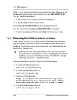
Restore from the database backup:

1. Click

Databases

and then select

Restore Databases …

from the con-

text menu.

The

Restore Databases

window opens:

346

ServerView Virtual-IO Manager

Summary of Contents for ServerView Virtual-IO Manager V3.1

Page 1: ...User Guide English ServerView Suite ServerView Virtual IO Manager V3 1 User Guide Edition October 2012 ...

Page 2: ...istently high quality standard and user friendliness this documentation was created to meet the regulations of a quality man agement system which complies with the requirements of the standard DIN EN ISO 9001 2008 cognitas Gesellschaft für Technik Dokumentation mbH www cognitas de Copyright and trademarks Copyright 1998 2012 Fujitsu Technology Solutions GmbH All rights reserved Delivery subject to...

Page 3: ...for blade servers 45 2 5 4 Virtualizing I O parameters 45 2 6 Server profile failover for blade servers only 47 2 7 High Availability HA support 48 3 Installation and uninstallation 57 3 1 Prerequisites for the VIOM installation 57 3 2 Installing the Virtual IO Manager on a Windows based CMS 58 3 2 1 Installing the Virtual IO Manager using a graphical interface 59 3 2 2 Installing the Virtual IO M...

Page 4: ... connection blades 101 4 1 4 Connecting IBP modules 104 4 1 4 1 Network Overview 105 4 1 4 2 Notes and recommendations 106 4 2 Configurations on the managed BX400 Blade Server 109 4 2 1 Supported hardware configurations for the connection blades 110 4 2 1 1 LAN hardware configuration 111 4 2 1 2 Fibre Channel hardware configuration 112 4 2 2 Configuring the BX400 management blade 113 4 2 3 Configu...

Page 5: ...ab 148 5 3 3 2 Details tab on Ext LAN Connections tab 150 5 3 4 Server Configuration tab 151 5 3 5 Chassis Configuration tab 156 5 3 6 Server Profiles view 158 5 4 Wizards 161 5 4 1 Create Network for IBP wizard only for blade servers 162 5 4 1 1 Select Type step Create Network wizard 163 5 4 1 2 Edit Properties step Create Network wizard internal network 164 5 4 1 3 Edit Properties step Create Ne...

Page 6: ...rd 207 5 4 4 3 IO Channels step Edit Server Profile wizard 208 5 4 4 4 Boot Parameter step Edit Server Profile wizard 212 5 4 4 5 CNA Parameter step Edit Server Profile wizard 218 5 4 4 6 Virtual Addresses step Edit Server Profile wizard 220 5 4 4 7 Confirm step Edit Server Profile wizard 222 5 4 5 Save Configuration wizard 223 5 4 5 1 Select Action step Configuration Backup Restore wiz ard 223 5 ...

Page 7: ...6 1 Starting the Virtual IO Manager 253 6 2 Closing Virtual IO Manager 253 6 3 Logging the actions using VIOM 254 6 3 1 Logging the actions on Windows 254 6 3 2 Logging the actions on Linux 256 7 Managing servers with VIOM 257 7 1 Activating management with VIOM 257 7 2 Changing access rights and ports 259 7 3 Deactivating management with VIOM 261 7 4 VIOM internal operations on blade servers 261 ...

Page 8: ...figurations 306 11 2 3 Restoring PRIMERGY rack server configurations 307 11 3 Deleting backup files on the management station 308 11 4 Restoring VIOM specific configurations 308 11 4 1 Restoring an IBP module configuration 308 11 4 2 Deleting the configuration of an uninstalled IBP module 309 11 4 3 Restoring the configuration of a server blade slot 310 11 4 4 Restoring the blade server chassis co...

Page 9: ... 1 2 Configuring the job schedule on Linux 342 14 1 3 Configuring the output directories 343 14 1 4 Starting the Backup Service on Windows 344 14 1 5 Starting the VIOM Backup Service on Linux 344 14 1 6 Logging the Backup Service 345 14 2 Restoring the VIOM database on Windows 345 14 2 1 Restoration via SQL Server Management Studio 345 14 2 2 Restoration via Enterprise Manager 349 14 2 3 Checking ...

Page 10: ...10 ServerView Virtual IO Manager ...

Page 11: ...ck servers centrally by the central management station using VIOM This includes virtualizing and for blade servers saving the server blade specific I O parameters MAC addresses WWN addresses I O connections includ ing the boot parameters and configuring and managing a blade server s Intel ligent Blade Panel in a hardware independent server profile This server profile can be assigned to a PRIMERGY ...

Page 12: ...on Windows and Linux plat forms and you install it using separate installation packages For more infor mation on VIOM CLI see the documentation entitled ServerView Virtual IO Manager Command Line Interface 1 1 Target groups and objective of this manual This manual is aimed at system administrators network administrators and service professionals who have a sound knowledge of hardware and soft ware...

Page 13: ... JRE version 7 0 update 7 or higher l Fire wall settings o Port 3172 must be opened for TCP IP connection to Remote Con nector Service o Port 162 must be opened to receive SNMP traps from iRMC when managing PRIMERGY rack servers You can also obtain the current requirements from the release notes You find the release notes e g on a Windows based management station under Start All Programs Fujitsu S...

Page 14: ...0 Server profiles without I O virtualization but with net work connection definition BX630 S2 Server profiles with I O virtualization and network connection definition Table 1 Supported server blades For information on the BIOS and iRMC firmware version see the release notes supplied The Virtual IO Manager can only manage BX600 chassis with S3 management blades MMB S3 that are assembled with the f...

Page 15: ...tions Server blade Scope of functions BX920 S2 BX920 S3 Server profiles with I O virtualization and network connection definition BX922 S2 Server profiles with I O virtualization and network connection definition BX924 S2 BX924 S3 Server profiles with I O virtualization and network connection definition Table 2 Supported server blades For information on the BIOS and iRMC firmware version see the r...

Page 16: ...on blades PY CB Eth Switch IBP 1 Gb 36 8 2 PY CB Eth Switch IBP 1 Gb 36 12 PY CB Eth Switch IBP 1 Gb 18 6 or PY CB Eth Switch IBP 10 Gb 18 8 in switch mode or IBP mode o LAN pass thru connection blades PY CB Eth Pass Thru 10 Gb 18 18 o FC switch blades of the type Brocade 5450 or o FC pass thru connection blades PY CB FC Pass Thru 8 Gb 18 18 l In fabric 3 same as fabric 2 The LAN connection blades...

Page 17: ...r profiles with I O virtualization and network connection definition BX922 S2 Server profiles with I O virtualization and network connection definition BX924 S2 BX924 S3 Server profiles with I O virtualization and network connection definition BX960 S1 Server profiles with I O virtualization and network connection definition Table 3 Supported server blades For information on the BIOS and iRMC firm...

Page 18: ...B Eth Switch IBP 1Gb 36 8 2 PY CB Eth Switch IBP 1Gb 36 12 PY CB Eth Switch IBP 1Gb 18 6 or PY CB Eth Switch IBP 10 Gb 18 8 in switch mode or IBP mode or o LAN pass thru connection blades PY CB Eth Pass Thru 10 Gb 18 18 o FC switch blades of the type Brocade 5450 o FC pass thru connection blades PY CB FC Pass Thru 8 Gb 18 18 l In fabric 3 same as fabric 2 l In fabric 4 same as fabric 1 The LAN con...

Page 19: ...X350 S7 TX300 S7 For information on the BIOS and iRMC firmware version see the release notes supplied The following PCI controllers are supported for all the above PRIMERGY rack server systems l Emulex 10GbE OCe10102 CNA l Emulex 8Gb FC HBA LPe 12002 l Emulex 8Gb FC HBA LPe 1250 1 channel l INTEL 2 port 10GbE D2755 Niantec l INTEL 4 port D2745 Barton Hills l INTEL 2 port D2735 Kawela 82576NS l INT...

Page 20: ...CSI initiator must be identical Excep tion physical port is completely disabled Emulex 8Gb FC HBA LPe 12002 Emulex 8Gb FC HBA LPe 1250 1 channel Assign virtual WWPN and WWNN Optionally define the first and second boot tar get and LUN Disable I O ports INTEL 2 port 10GbE D2755 Niantec INTEL 4 port D2745 Bar ton Hills INTEL 2 port D2735 Kawela 82576NS INTEL Eth Ctrl 4x1Gb Cu PCIe x4 D3045 INTEL Eth ...

Page 21: ...90 and IO Channels step Edit Server Profile wizard on page 208 l DCB settings also possible for iSCSI see CNA Parameter step Create Server Profile wizard on page 200 and CNA Parameter step Edit Server Profile wizard on page 218 l Video Redirection for server blades and rack servers see Server Con figuration tab on page 151 l User specific display properties are stored session independent see Prefe...

Page 22: ...ew update agents for updating the PRIMERGY servers via Server View Update Manager or for locally updating individual servers via ServerView Update Manager Express o The current versions of all documentation on the ServerView Suite You can retrieve the downloads free of charge from the Fujitsu Tech nology Solutions Web server For PRIMERGY servers links are offered on the following topics l Service ...

Page 23: ...te DVD 1 select the option Select ServerView Software Products l Click Start This takes you to the page with the software products of the ServerView Suite l On the menu bar select Links This opens the start page of the ServerView link collection 1 6 Documentation for the ServerView Suite The documentation for the ServerView Suite can be found on the ServerView Suite DVD 2 supplied with each server...

Page 24: ...ous text Indicates a link to a related topic pink con tinuous text Indicates a link to a location you have already visited abc Indicates variables which must be replaced with real values abc Indicates options that can be specified syntax key Indicates a key on your keyboard If you need to enter text in uppercase the Shift key is specified for example SHIFT A for A If you need to press two keys at ...

Page 25: ...reas from each other it is necessary to keep the I O parameters MAC and WWN outwardly constant Using virtual addresses instead of the MAC addresses or WWN addresses stored on the NIC network interface card or in the HBA the addressing remains constant even when a server blade is exchanged at the slot or a PRIMERGY rack server is replaced by another one 2 2 Special connection blade for blade server...

Page 26: ... and as a result the switches have to be reconfigured The onboard LAN and FC controllers in the server blade are connected to the installed LAN or FC switches via a midplane and are in turn connected to the LAN and SAN network via their uplink ports Providers use specific pro tocols or protocol extensions for switches from different manufacturers which can lead to interoperability problems between...

Page 27: ...way mode FC AG l For LAN BX600 BX600 GbE Intelligent Blade Panel 30 12 or 10 6 IBP GbE BX400 BX900 Connection Blade PY CB Eth Switch IBP 1Gb 36 8 2 PY CB Eth Switch IBP 1Gb 36 12 PY CB Eth Switch IBP 1Gb 18 6 or PY CB Eth Switch IBP 10 Gb 18 8 in the IBP mode The connection blades can run in switch mode in IBP mode or in End Host Mode EHM These connection blades offer the advantage of a switch cab...

Page 28: ... Virtual IO Manager VIOM to manage the con nection blades of a blade server and to maintain the relevant I O parameters constant at the chassis slot of a blade server or at the PRIMERGY rack server VIOM is installed on the central management station and integrated in the ServerView Operations Manager 28 ServerView Virtual IO Manager ...

Page 29: ... VIOM essentially includes the following functions l Defining the I O parameters including virtual addresses of a PRIM ERGY rack server l Saving the I O parameters in server profiles l Assigning the server profiles to a PRIMERGY rack server Before you can execute the functions above a blade server chassis or PRIM ERGY rack server must be managed by VIOM You also do this using the GUI of the Virtua...

Page 30: ...is on which uplink ports This also makes it possible to separate individual server blades or groups of server blades from a network perspective so that two server blade groups do not have any connection to each other in terms of network Defining network paths on an IBP module includes the following steps l Defining an uplink set An uplink set comprises one or several uplink ports An uplink port is...

Page 31: ...is by VIOM IBP connection blades should be set to factory default setting except IP address con figuration of the administrative interface user assigned name and access protocol SSH or telnet By default the IBP module IBP 10 6 is supplied with the following con figuration Figure 3 Standard configuration of the IBP module 10 6 All uplink ports of the IBP module IBP 10 6 are combined in one uplink s...

Page 32: ... a LAN connection blade This gives you several inde pendent network paths e g for different applications e g database server communication server or individual areas e g development accounting or personnel administration To find out what happens when you activate the management of a blade server using the Virtual IO Manager with the standard IBP con figuration see section VIOM internal operations ...

Page 33: ...one of these as an active port and the other as a backup port In this case the active port switches to the backup port if an error occurs linkdown event for all active ports In the figure shown this could be the uplink sets 1 and 2 if for each of these one port of the uplink set is configured as an active port and one port as a backup port l Link aggregation group By grouping several active uplink...

Page 34: ...l networks with VLAN IDs VLAN networks l Virtual networks with VLAN IDs native VLAN ID VLAN networks l Service LAN Dedicated service network l Service VLAN Service VLAN networks The network types in bold indicate their corresponding names in the VIOM GUI Internal networks An internal network refers to a network connection within the IBP in which server blades are only linked to each other However ...

Page 35: ... networks as there are uplink ports If networks are to be created with backup ports or with a link aggregation group then the number of possible networks on an IBP module is automatically reduced You can get around this restriction regarding the uplinks that are physically available by defining virtual networks Virtual Local Area Network VLAN By setting up virtual networks which can be identified ...

Page 36: ...ks with the VLAN ID 20 these are two different virtual networks Server blade 2 can not communicate with server blade 3 Packets that come from outside the network which have a VLAN tag that corresponds to the VLAN ID of a virtual network are transferred in precisely this VLAN network Before the packet exits the module on the server blade side the VLAN tag of a virtual network is removed in the same...

Page 37: ...ts when the network is used in tagged mode see Virtual net works with VLAN ID used in tagged mode on page 38 Virtual network with a VLAN ID as native VLAN You can select a virtual network of a shared up link set as the default or native VLAN All packages that do not contain a VLAN ID will be allowed through this connection Packets that come from outside the network which do not have a VLAN tag are...

Page 38: ...r blade 1 Virtual networks with VLAN ID used in tagged mode While normally the VLAN IDs of packets that leave the IBP on the server blade side are removed it is possible to use a VLAN network in tagged mode This means that all packets retain their VLAN tag when they are trans mitted to the server blade Packets that arrive on the server blade side of the IBP must have a VLAN tag with the correspond...

Page 39: ...k is used is controlled by network def initions in a server profile It cannot be specified within the network settings The advantage of the tagged mode is that the same VLAN networks can be used either untagged for separate server blades on different downlinks or tagged for one server blade with separate virtual machines on one downlink ServerView Virtual IO Manager 39 2 4 Defining networks LAN fo...

Page 40: ...o be configured to use a VLAN tag for its LAN packets A dedicated service network defined with the same VLAN ID as used by the iRMC allows the tagged iRMC LAN packets to be routed to specific uplink port s external port s whereas the other LAN packets from the operating system are routed to a separate uplink port In addition the dedicated service network can also be used to route the LAN packages ...

Page 41: ...rks may overlap on the downlink ports with single networks VLAN networks other dedicated service networks and Service VLAN networks explained below The untagged packets received from the server blade or uplink port should obey the rule of the single network or VLAN network that overlaps with the dedicated service network The VLAN tags of the overlapping VLAN networks dedicated serv ice networks an...

Page 42: ...must be configured to send their packages with a VLAN tag that is identical to the Service VLAN ID of the Service VLAN network The behavior of a Service VLAN network is such that it receives tagged pack ets with the Service VLAN ID from the server blade and forwards them to uplink ports as tagged packets The LAN packages leave the IBP tagged at the uplink ports Incoming tagged packets with the Ser...

Page 43: ...uplink ports with VLAN networks The VLAN tag of Service VLAN networks and VLAN networks sharing the same uplink ports must be different 2 5 Server profiles A server profile contains the following VIOM specific parameters 1 Defining the connection in external networks see section Defining net work paths LAN on page 277 only for blade servers 2 Defining the physical identity in the form of I O addre...

Page 44: ...ardware under a user defined name in a server profile repository on the central management station 2 5 2 Assigning server profiles The server profiles that are stored in the central server profile repository can be assigned to the slots of a blade server or to a PRIMERGY rack server using VIOM In order to do this the blade server or PRIMERGY rack server must be managed by VIOM In addition you must...

Page 45: ...g I O parameters Virtualizing the physical server identity in the form of physical MAC address es WWN addresses and boot parameters is a key function of the Server View Virtual IO Manager software By defining virtual I O addresses and boot parameters as part of a server pro file you can easily move an operating system image or an application from one server blade or PRIMERGY rack server to another...

Page 46: ...ses for a slot is switched off e g if the corresponding server profile is moved If the central management server is switched off or the connection between the management station and the management blade is interrupted all the blade servers use the configuration last defined Once the connection to the external networks is configured and the server profiles assigned with virtualization parameters by...

Page 47: ... same blade server In order to do this you must define spare slots that assume the tasks of the other server blade in such a case It is advisable to install server blades at the spare slots so that they are available if a problem occurs or maintenance work needs to be carried out A failover of this type can only take place if the server blade on which the failover is to take place is switched off ...

Page 48: ...ows Server oper ating system This means that the ServerView management station is a virtual machine run ning on a Windows 2008 Hyper V cluster or in a VMware HA environment High availability of Hyper V cluster The following Hyper V high availability configurations will be supported Operating system Admin server if HA Guest OS Hypervisor Windows Server 2003 R2 Enterprise x86 x64 SP2 or higher P Win...

Page 49: ...min server and guest OS on VM To set up the Windows 2008 Hyper V cluster and the virtual machine that will be controlled from it click here for the Microsoft instructions http technet microsoft com en us library cc732181 28v ws 10 29 aspx If there is a fault in the Hyper V cluster node the Microsoft cluster will per form a failover action of the Hyper V environment to the other cluster node and re...

Page 50: ... proceed as follows On the primary node 1 Connect with shared storage 2 Configure BIOS 3 Install Hyper V roles 4 Install and configure EMC Solutions Enabler if used 5 Add a failover clustering function 6 Create a Hyper V virtual network 7 Create clusters 8 Prepare virtual machines 9 Register virtual machines in clusters 10 Install and configure storage management software 11 Install and configure ...

Page 51: ... a Hyper V virtual network 10 Create clusters 11 Prepare virtual machines 12 Register virtual machines in clusters 13 Operate the management station in a cluster For details of items 7 to 13 refer to the Hyper V manual If an error occurs on a VM guest the operation will continue if the VM guest is switched over High availability of VMware HA To make use of the high availability functionality of VM...

Page 52: ...2 Virtual IO Manager Introduction Figure 12 Architecture and typical configuration of VMware Infrastructure 3 52 ServerView Virtual IO Manager ...

Page 53: ...orted by Virtual IO Manager by the following meas ures l The central ServerView Virtual IO Manager service is configured to be restarted automatically in the event of failure This automatic restart of the service is configured during installation of Virtual IO manager By default the following restart behavior is configured o The first restart of the service is tried 5 seconds after unexpected ter ...

Page 54: ...cted ter mination of the service o The second restart is tried 30 seconds after termination of the serv ice o Subsequent restarts are tried 120 seconds after termination of the service o The restart counter is reset after 600 seconds The details of this configuration cannot be seen via the nor mal graphical user interface of the service manager To see the details you must use the command line inte...

Page 55: ... IO Manager client the changes will not be undone l The transaction concept of the Virtual IO Manager should allow you to restart the service and execute the described undo actions if the data base is not corrupted by the SQL database service used What Virtual IO Manager does not do Virtual IO Manager does not control the availability of the ServerView Virtual IO Manager service It also does not c...

Page 56: ...56 ServerView Virtual IO Manager ...

Page 57: ... a Windows based CMS on page 72 and Updating the Virtual IO Manager on a Linux based CMS on page 89 If you want to use the command line interface of the Virtual IO Manager VIOM CLI you must install the VIOM CLI software package You will find details on how to install and use VIOM CLI in the Virtual IO Manager Com mand Line Interface manual 3 1 Prerequisites for the VIOM installation The requiremen...

Page 58: ...s o Port 3172 must be opened for TCP IP connection to Remote Con nector Service o Port 162 must be opened to receive SNMP traps from iRMC when managing PRIMERGY rack servers You can also obtain the current requirements from the release notes You find the release notes e g on a Windows based management station under Start All Programs Fujitsu ServerView Suite Virtual IO Manager Release Notes 3 2 In...

Page 59: ...y of the DVD ROM 2 Select the option ServerView Software Products 3 Click Start 4 In the next window select the required language 5 Select ServerView Virtual IO Manager 6 Double click the SV_VIOM exe The installation wizard is launched After determining a number of parameters of the existing operating sys tem base the following window is displayed ServerView Virtual IO Manager 59 3 2 Installing th...

Page 60: ...3 Installation and uninstallation 7 Click Next Accept the license agreement by selecting the corresponding option 60 ServerView Virtual IO Manager ...

Page 61: ...organization You must also specify whether the settings should only apply for the current user or for any user working on this system Select the corresponding option ServerView Virtual IO Manager 61 3 2 Installing the Virtual IO Manager on a Windows based CMS ...

Page 62: ...l address es in server profiles you must have already defined address ranges here 10 Click Next If you did not select Select address ranges for IO Virtualization in the previous window clicking Next brings you to the Ready to Install the Application window in which you start the installation If you selected Select address ranges for IO Virtualization the fol lowing window opens 62 ServerView Virtu...

Page 63: ...0 MAC addresses If such a range is insufficient you can also select a range double the size using MAC Address Range 1 and 2 to MAC Address Range 7 and 8 Each of these areas contains 16000 MAC addresses If you have an address range of your own that you wish to use for virtual MAC addresses then select it in the Custom MAC Address Range drop down menu In this case the fields in Custom MAC Address Ra...

Page 64: ...sed do not overlap Otherwise addresses may be assigned several times To change the range of the address after installation is finished you must uninstall the Virtual IO Manager and install it again Therefore if it is possible that addresses may have to be added after the Virtual IO Manager is set up we recommend that you install it without selecting the address range You should input a virtual add...

Page 65: ...ase the fields in Custom WWN Address Range Param eters in which you can enter the start and end WWN address become active The validity of the WWN address input is not checked Please confirm that your input address is valid before you click Next If you have several installations of the Virtual IO Manager in your Storage network then you must ensure that the address ranges used do not overlap Otherw...

Page 66: ...nd uninstallation 12 Click Next Once you have made all your entries click Next to start the installation If you want to make further changes click Back to return to the previous window 66 ServerView Virtual IO Manager ...

Page 67: ...allation of the Virtual IO Manager is started The fol lowing window is then displayed 14 Click Next to launch the License Manager ServerView Virtual IO Manager 67 3 2 Installing the Virtual IO Manager on a Windows based CMS ...

Page 68: ...he VIOM License Manager dialog box to exit the License Manager The dialog box closes 17 Click Finish to end the installation 3 2 2 Installing the Virtual IO Manager using the command line interface The Virtual IO Manager can be installed using the command line interface You start the installation via the installation package SV_VIOM exe which you will find on the ServerView Suite DVD 1 under Serve...

Page 69: ...s are NONE No predefined MAC address range default value MAC1 Range 00 19 99 3E D2 A1 00 19 99 3E F1 E0 MAC2 Range 00 19 99 3E F1 E1 00 19 99 3F 11 20 MAC3 Range 00 19 99 3F 11 21 00 19 99 3F 30 60 MAC4 Range 00 19 99 3F 30 61 00 19 99 3F 4F A0 MAC5 Range 00 19 99 3F 4F A1 00 19 99 3F 6E E0 MAC6 Range 00 19 99 3F 6E E1 00 19 99 3F 8E 20 MAC7 Range 00 19 99 3F 8E 21 00 19 99 3F AD 60 ServerView Vir...

Page 70: ... 3F CC A1 MAC_CUSTOM Custom range must be set with the MAC_START and MAC_END parameters MAC_START MAC_END These parameters must be set if MAC_Custom is specified The values must be in hexadecimal format for example 11 22 33 44 55 66 WWN_RANGE Possible values are NONE No predefined WWN address range default value WWN1 Range 50 01 99 93 ED 2A 10 00 50 01 99 93 EF 1E 0D FF WWN2 Range 50 01 99 93 EF 1...

Page 71: ...ange 50 01 99 93 FA D6 02 00 50 01 99 93 FC CA 00 00 WWN_CUSTOM Custom range must be set with the WWN_START and WWN_ END parameters WWN_START WWN_END These parameters must be set if WWN_Custom is specified The values must be in hexadecimal format for example 11 22 33 44 55 66 77 88 DEBUG_MODE Possible values are true Enable debug mode default value false Disable debug mode VIOM_LICENSE_KEY The lic...

Page 72: ...bcdef 3 3 Updating the Virtual IO Manager on a Windows based CMS If you have already installed a previous version an update installation runs automatically when you install the Virtual IO Manager In this case all user specific configurations and definitions remain the same An update installation starts in the same way as a full installation see sec tion Installing the Virtual IO Manager on a Windo...

Page 73: ...VD1 You can find the entire software for the PRIMERGY Server View Suite under ServerView Software Product Selection To find the Vir tual IO Manager software package like 3 1 0_2012 08 15 zip in this product selection choose ServerView Virtual IO Manager Please check the requirements for installing the Virtual IO Manager to see whether the Linux distribution you use is supported by the Virtual IO M...

Page 74: ...n on page 57 Installation process 1 Set the DISPLAY environment variable export DISPLAY IP address host name 0 0 Example export DISPLAY 111 22 33 115 0 0 2 If you prefer to have a dedicated directory for each VIOM package create one e g root VIOM_3 1 0 and copy the zip file e g VIOM_ 3 1 0 2012 08 15 zip from the installation medium to that directory and unzip it mkdir root VIOM_3 1 0 cp VIOM_3 1 ...

Page 75: ...After these preparations start the installation by launching the GUI sh install_viom sh The welcome window opens ServerView Virtual IO Manager 75 3 4 Installing the Virtual IO Manager on a Linux based CMS ...

Page 76: ...3 Installation and uninstallation 4 Click Next Accept the license agreement by selecting the corresponding option 76 ServerView Virtual IO Manager ...

Page 77: ...5 Click Next Enter your name and the name of your company organization ServerView Virtual IO Manager 77 3 4 Installing the Virtual IO Manager on a Linux based CMS ...

Page 78: ...tion and uninstallation 6 Click Next Enter the data on the ServerView database The database user svuser has been created during ServerView installation and is used by VIOM as well 78 ServerView Virtual IO Manager ...

Page 79: ...address es in server profiles you must have already defined address ranges here 8 Click Next If you did not select Select address ranges for IO Virtualization in the previous window clicking Next brings you to the Ready to Install the Application window in which you start the installation ServerView Virtual IO Manager 79 3 4 Installing the Virtual IO Manager on a Linux based CMS ...

Page 80: ...verlap MAC Address Range 1 to MAC Address Range 8 Each of these address ranges contains 8000 MAC addresses If such a range is insufficient you can also select a range double the size using MAC Address Range 1 and 2 to MAC Address Range 7 and 8 Each of these areas contains 16000 MAC addresses If you have an address range of your own that you wish to use for virtual MAC addresses then select it in t...

Page 81: ...address ranges used do not overlap Otherwise addresses may be assigned several times To change the range of the address after installation is finished you must uninstall the Virtual IO Manager and install it again Therefore if it is possible that addresses may have to be added after the Virtual IO Manager is set up we recommend that you install it without selecting the address range You should inp...

Page 82: ...n the Custom WWN Range drop down menu In this case the fields in Custom WWN Address Range Param eters in which you can enter the start and end WWN address become active The validity of the WWN address input is not checked Please confirm that your input address is valid before you click Next If you have several installations of the Virtual IO Manager in your Storage network then you must ensure tha...

Page 83: ...n click OK l The licenses are not version bound l Licenses purchased with Virtual IO Manager versions prior to V2 4 are also still valid These licenses v1 contain a chassis count which is multiplied by 18 to get the assign count used in licenses v2 purchased with Virtual IO Man ager V2 4 or later 12 Click Exit in the VIOM License Manager dialog box to exit the License Manager The dialog box closes...

Page 84: ...d here You find the script in the directory where you unzipped the VIOM software package see Installing the Virtual IO Manager using a graphical interface on page 74 Simply use the no gui switch and enter suitable parameters The following syntax is supported sh install_viom sh dbhost ip address hostname dbport port number dbuser username dbpasswd password mac range first mac addr last mac addr MAC...

Page 85: ...Operations Man ager database has no password mac range MAC address range Custom range must be set with the MAC start address and the MAC end address The values must be in hexadecimal format for example 11 22 33 44 55 66 Predefined MAC address ranges must be separated by a comma Pos sible values for predefined MAC address ranges are MAC1 Range 00 19 99 3E D2 A1 00 19 99 3E F1 E0 MAC2 Range 00 19 99...

Page 86: ... 00 19 99 3F 11 20 MAC34 Range 00 19 99 3F 11 21 00 19 99 3F 4F A0 MAC56 Range 00 19 99 3F 4F A1 00 19 99 3F 8E 20 MAC78 Range 00 19 99 3F 8E 21 00 19 99 3F CC A1 wwn range WWN address range The values for a custom address range must be in hexadecimal format for example 11 22 33 44 55 66 77 88 Predefined WWN address ranges must be separated by a comma Pos sible values for predefined WWN address ra...

Page 87: ...6 00 50 01 99 93 F8 E2 03 FF WWN7 Range 50 01 99 93 F8 E2 04 00 50 01 99 93 FA D6 02 FF WWN8 Range 50 01 99 93 FA D6 02 00 50 01 99 93 FC CA 00 00 no gui Run installation in console mode non gui installation license key The license key for the Virtual IO Manager check prerequisites Only check prerequisites and exit lang VIOM installation language Possible values en English ServerView Virtual IO Ma...

Page 88: ...tails in the log files Example sh install_viom sh no gui dbhost 127 0 0 1 dbport 9212 mac range 00 19 99 3E D2 A1 00 19 99 3E F1 E0 wwn range 50 01 99 93 ED 2A 10 00 50 01 99 93 EF 1E 0D FF license key AAA BBBB CCCC DDDD EEEE FFFF GGGG 3 4 3 Important directories of Virtual IO Manager opt fujitsu ServerViewSuite plugins viom In all Linux distributions this is the installation directory where the b...

Page 89: ...y var fujitsu ServerViewSuite viom dumps 3 5 Updating the Virtual IO Manager on a Linux based CMS If you have already installed a previous version you can run an update instal lation In this case you must specify the upgrade option when invoking the installation script sh install_viom sh upgrade When running an update installation all user specific configurations and def initions remain the same A...

Page 90: ...order to use VIOM You purchase licenses for a certain number of server profiles that can be assigned to server blades using VIOM l The licenses are not version bound l Registered licenses for an installed Virtual IO Manager version prior to V2 4 are multiplied internally by 18 This means that the chassis count of these licenses v1 is converted x18 into the assign count used in licenses v2 used as ...

Page 91: ...irtual IO Manager on a Windows based CMS on page 58 and periodically during the running time of the VIOM service On Windows you can also launch the License Manager the tool for man aging licenses separately from the Windows Start Menu e g to specify new or additional licenses On Linux you can also launch the License Manager by starting the license sh script which you find in the installation direc...

Page 92: ... IO Manager V2 4 or later 3 Click Exit in the VIOM License Manager dialog box to exit the License Manager On Linux you can also add a licence without graphical user inter face cd opt fujitsu ServerViewSuite plugins viom Manager sh license sh license key key no gui You can also delete licenses provided that the total number of assignments of the remaining licenses is not smaller than the number of ...

Page 93: ...viom Manager java jar VIOM LICENSE MANAGER jar remove key In addition to using the License Manager to manage licenses you can dis play the licenses assigned in the Virtual IO Manager interface To do this you must click the Show Licenses button on the Virtual IO Manager tab You use the Show Licenses button on the Virtual IO Manager tab to request information on the licenses assigned 1 To do this cl...

Page 94: ...n on page 275 3 7 Updating ServerView Operations Manager ServerView Operations Manager may be updated at any time while the Vir tual IO Manager is idle Thus you should stop the Virtual IO Manager Service before starting the update Updating ServerView Operations Manager consists of three steps l Perform an update installation of ServerView Operations Manager l Check that the updated version works o...

Page 95: ...nagement station CMS or on a remote node The following is based on that information In chapter Upgrade installations of SQL Server two major cases are distinguished l Upgrading an SQL Server instance while keeping the instance name l Moving an SQL Server instance to an instance with a different name In the former case there there is one thing to add if the Virtual IO Manager is running on the cent...

Page 96: ...Virtual IO Manager on a Windows based CMS You uninstall the Virtual IO Manager via the Windows start menu l On Windows Server 2003 Select Start Settings Control Panel Add Remove Programs l On Windows Server 2008 Select Start Control Panel Programs and Features To display the product versions select Choose Details from the View menu Select the Version option and click OK Under Fujitsu ServerView Vi...

Page 97: ...ction blades see section Configuring the I O connection blades on page 101 l Define the connection of the IBP modules with the network see section Connecting IBP modules on page 104 l Add the blade server to the server list of the ServerView Operations Man ager see section Adding a server to the ServerView server list on page 135 4 1 1 Supported hardware configurations for the connection blades To...

Page 98: ...ns are sup ported in Fabric 1 and 2 Bay 1 Bay 3 Bay 2 Bay 4 IBP 10 6 IBP 10 6 optional IBP 30 12 IBP 30 12 optional1 1 Even though this constellation is possible it does not make sense because only the first port can be used from the IBP 30 12 in bay 1 or bay 3 You can also use different IBP modules within one fabric In this con stellation however not all downlinks can be used by the larger model ...

Page 99: ...ormal switch mode l in Access Gateway mode As a result different combination options are possible The following table shows you which configurations are possible and which are supported in fab ric 2 Bay 3 Bay 4 Access Gateway mode Access Gateway mode Standard switch mode Standard switch mode Access Gateway mode Access Gateway mode Standard switch mode Standard switch mode 4 1 2 Configuring the BX6...

Page 100: ...nagement blade For a MMB S3 choose 4 TFTP update 6 Management Blade Update Enable After selecting 5 TFTP Update in 4 Management Blade Image File Name you first specify the name of the firmware file with the new firm ware version l You must configure the management blade and connect it to the local net work so that it can be accessed from the central management station on which the ServerView Opera...

Page 101: ...g the I O connection blades The IBP modules in fabric 1 and the optional connection blades IBP or Bro cade Fibre Channel switch blades in fabric 2 must be configured and con nected to the local network so that they can be accessed from the central management station on which the ServerView Operations Manager and VIOM are installed You can configure the network parameters of an I O connection blade...

Page 102: ...gement blade You configure the network parameters of an I O connection blade as follows l In DHCP Enable select whether the connection blade should be given its IP address from an DHCP server or not If you select NO DHCP you must enter the IP address subnet mask and the gateway address l Click Apply to activate the settings 102 ServerView Virtual IO Manager ...

Page 103: ...lade as follows l In the Remote Manager choose 1 Management Agent 6 Con nection Blade l Select an I O connection blade l Make the relevant entries for the following parameters o IP Mode Setting Value o IP Address Setting Value o Subnet Mask Setting Value o Gateway Setting Value l Activate the settings by clicking Apply Network Setting ServerView Virtual IO Manager 103 4 1 Configurations on the man...

Page 104: ...ther words the first external LAN port Here the management LAN is the network to which the central management station is connected and via which you can access the management blades and all I O connection blades The first uplink port is always the external uplink port of an IBP module on the very right of the upper row as seen from behind Figure 14 First uplink port of an IBP module For an IBP 10 ...

Page 105: ...e blade server with VIOM has been acti vated This is because the first six or first eight uplink ports form a static link aggregation group LAG in the IBP standard configuration 4 1 4 1 Network Overview All components such as the management blades and I O connection blades the central management station and the management console must be inter connected via LAN It is recommended that you set up a ...

Page 106: ...ent station 4 1 4 2 Notes and recommendations We recommend that you do not use the first uplink port in the network def initions If you cannot avoid doing so then you must note the following l The speed definition used must remain set to auto negotiate l The network that uses this uplink port must not be deleted 106 ServerView Virtual IO Manager ...

Page 107: ...elnet 10 10 10 50 3172 l Enter the authentication data for the management blade l In the Remote Manager choose 3 Console Redirection 2 Con sole Redirect Connection Blade l Select the affected I O connection blade e g 1 Console Redirect GbE IBP Blade 1 l You are now connected to the selected I O connection blade To access the connection blade from the central management station the first uplink por...

Page 108: ...default 1_INTERN_1 1_INTERN_2 1_NET 0 1 0 2 1_NET 0 11 1_NW1 1_NW1 0 12 0 13 0 14 1_NW2 1_NW2 0 15 0 16 In the above example the first uplink port 0 11 belongs to the uplink set 1_ NET and the port group 1_NET is assigned to this uplink set If port 0 11 does not belong to any uplink set but should belong to uplink set 1_NET then enter the following commands Vty 0 configure Vty 0 Config interface 0...

Page 109: ... server chassis The details for the IBP module and the Restore IBP button are then dis played at the bottom on the right l Click the Restore IBP button The IBP module is then programmed according to the configuration saved in VIOM 4 2 Configurations on the managed BX400 Blade Server In section Supported hardware configurations for the connection blades on page 110 you can find out what combination...

Page 110: ...3 and 4 of fabric 3 in order to connect the LAN ports of the second mez zanine card To define dedicated network connections for server blades with net works you require LAN connection blades in IBP mode The PY CB Eth Switch IBP 1Gb 36 8 2 PY CB Eth Switch IBP 1Gb 36 12 PY CB Eth Switch IBP 1Gb 18 6 and PY CB Eth Switch IBP 10 Gb 18 8 con nection blades support a normal Layer 2 switch mode and IBP ...

Page 111: ... Eth Switch IBP 1Gb 36 8 2 in IBP mode optional1 PY CB Eth Switch IBP 1Gb 36 12 in IBP mode PY CB Eth Switch IBP 1Gb 36 12 in IBP mode optional1 PY CB Eth Switch IBP 1Gb 18 6 in IBP mode PY CB Eth Switch IBP 1Gb 18 6 in IBP mode optional1 PY CB Eth Switch IBP 10 Gb 18 8 in IBP mode PY CB Eth Switch IBP 10 Gb 18 8 in IBP mode optional1 1 Even though this constellation is possible it does not make s...

Page 112: ... fabric 3 although you cannot use all download links from the larger model 4 2 1 2 Fibre Channel hardware configuration You can install the Fibre Channel switch blades in fabric 2 or fabric 3 They can be operated in two different modes l in normal switch mode l in Access Gateway mode As a result different combination options are possible Fabric 2 and fabric 3 have identical configuration restricti...

Page 113: ...ace of the management blade Open the Information Operation section on the left side and select Firmware Update within Operation l You must configure the management blade and connect it to the local net work so that the management LAN port of the management blade can be accessed from the central management station on which the ServerView Operations Manager and VIOM is installed l Access to the mana...

Page 114: ...gured 4 2 3 Configuring the I O connection blades The connection blades in fabric 1 and the optional connection blades in fabric 2 and 3 must be configured and connected to the local network so that they can be accessed from the central management station on which the Server View Operations Manager and VIOM are installed You can configure the network parameters of an I O connection blade using the...

Page 115: ...et mask and the gateway address l Click Apply to activate the settings 4 2 4 Connecting IBP modules The PY CB Eth Switch IBP 1Gb 36 8 2 PY CB Eth Switch IBP 1Gb 36 12 LAN PY CB Eth Switch IBP 1Gb 18 6 and PY CB Eth Switch IBP 10 Gb 18 8 connection blades support two modes l Normal Layer 2 switch mode l IBP mode For information on how to perform the switch refer to the Switch Blade user manual Serv...

Page 116: ...tivated when networks are defined in the IBP module 4 2 4 1 Network Overview All components such as the management blades and I O connection blades the central management station and the management console must be inter connected via LAN It is recommended that you set up a management LAN that is separate from the productive LAN as illustrated in the following figure If there are not enough physica...

Page 117: ...band CX4 interface of the HiGig HiGig ports One of the IBP s controlled the operation of the stack modules is called the stack master Other IBP s are belonging to the stack members of the stack group system The stacking software configures each device tables and registers to support all switching functions for example switching link aggregation port ServerView Virtual IO Manager 117 4 2 Configurat...

Page 118: ...k select one stack member and start the desired operation Details can be found in Defin ing network paths LAN on page 277 4 3 Configurations on the managed BX900 Blade Server In section Supported hardware configurations for the connection blades on page 119 you can find out what combinations of I O connection blades are supported by VIOM To manage a blade server with VIOM you must carry out the fo...

Page 119: ...Y CB Eth Switch IBP 1Gb 36 8 2 PY CB Eth Switch IBP 1Gb 36 12 PY CB Eth Switch IBP 1Gb 18 6 and PY CB Eth Switch IBP 10 Gb 18 8 con nection blades support a normal Layer 2 switch mode and IBP mode If you only intend to work with virtual I O parameters Open Fabric mode of the Virtual IO Manager and not with dedicated network connections you can also use the connection blades in switch mode or you c...

Page 120: ... use of non VIOM capable LAN modules together with the Virtual IO Manager In this case you can only work with vir tual I O parameters and not with dedicated network connections Therefore if you do not want to use any routing all combinations are possible even with non VIOM capable I O connection blades You must take the fol lowing into account l You cannot mix LAN and IBP modules within a fabric l...

Page 121: ...2 Configuring the BX900 management blade The blade server must be fitted with at least one S1 management blade The management blade has two user friendly user interfaces a Web inter face and a Remote Manager interface per Telnet or SSH protocol a con nection to the management blade is established per Telnet or SSH You can find a detailed description on the interfaces in the ServerView Management B...

Page 122: ... the management blade via Telnet or SSH is essential for VIOM You must configure the management blade via its Web interface To do this choose Settings System Unit Network Interface Management LAN On the Ethernet tab check the telnet and SSH set tings in the Text based Access section l Ensure that the Automatic Inventory Retrieval parameter is set to automatic so that the management blade automatic...

Page 123: ...etwork so that they can be accessed from the central management station on which the ServerView Operations Manager and VIOM are installed You can configure the network parameters of an I O connection blade using the easy to use Web interface or you can use the Remote Manager of the management blade Configuration using the Web interface It is important that the I O connection blades of the BX900 ca...

Page 124: ...s to receive its IP address from a DHCP server If this option is not activated you must specify the IP address subnet mask and the gateway address l Click Apply to activate the settings Configuration using the Remote Manager You can also configure the network parameters of the I O connection blades using the Remote Manager of the management blade 124 ServerView Virtual IO Manager ...

Page 125: ... Setting Value o IP Address Setting Value o Subnet Mask Setting Value o Gateway Setting Value l Activate the settings by clicking Apply Management port Network Set ting For Fibre Channel switch modules select FC Switch Blade you must also specify access data for the parameters Set Login Username and Set Login Password beforehand for the corresponding I O connection blade in the management blade Se...

Page 126: ...m a stat ic link aggregation group LAG If you activate blade server management using VIOM all uplink ports of IBP modules will be deactivated and will only be reactivated when networks are defined in the IBP module 4 3 4 1 Network Overview All components such as the management blades and I O connection blades the central management station and the management console must be inter connected via LAN...

Page 127: ...ort A stacking function is a group set of IBP s connected through Infiniband CX4 interface of the HiGig HiGig ports One of the IBP s controlled the operation of the stack modules is called the stack master Other IBP s are belonging to the stack members of the stack group system ServerView Virtual IO Manager 127 4 3 Configurations on the managed BX900 Blade Server ...

Page 128: ... stacked SB11 Connection Blades in IBP Mode VIOM also supports stacked SB11 connection blades in IBP mode but the configured stack must not span over several chassis Stacked SB11 con nection blades in switch mode are also supported since VIOM handles them transparently In this case the stack can span over several chassis For correct handling by VIOM the SNMP agent on the stacked SB11 con nection b...

Page 129: ... conditions are not fulfilled VIOM will not be able to handle the stack correctly l Update the information for this blade server chassis in ServerView Oper ations Manager by performing the explore action for the blade server chassis l Perform the Refresh action in VIOM user interface so that also VIOM has the updated information about the changed configuration The last two actions will also be don...

Page 130: ...ou must configure a static IP address net mask and default gateway manually for the iRMC of every PRIMERGY rack server that is to be managed by VIOM l The PRIMERGY rack server and especially the iRMC must be added to the server list of ServerView Operations Manager ServerView Oper ations Manager must be configured in such a way that it can com municate with the iRMC This means that ServerView Oper...

Page 131: ...perations Manager should have SNMP access to the server It is preferable to install ServerView agents on the operating system When managing multiple PRIMERGY rack servers via VIOM the vir tualization of the I O ports together with the definition of the boot device con figuration Fibre Channel boot iSCSI boot PXE boot by VIOM allows easy shifting of an application OS boot image from one server to a...

Page 132: ...ssible it is important to know how I O channels of blade server mezzanine cards are mapped to I O channels of PCI add on cards and vice versa Onboard I O channels are taken as they are Of course the device type of the destination ports have to be compatible to the source ports The used I O channel mapping is shown in the following table Mezzanine card in blade server PCI controller in PRIMERGY rac...

Page 133: ...gnored when the profile is assigned to a PRIMERGY rack server 4 6 PCI slot location in PRIMERGY rack servers The PCI slots of the supported PRIMERGY rack servers are located as fol lows RX200 S7 Figure 19 RX200 S7 connection panel on the rear 1 PCI slot 3 2 PCI slot 2 3 PCI slot 1 4 Management LAN connector iRMC 5 Standard LAN connector LAN 2 6 Shared LAN connector LAN 1 ServerView Virtual IO Mana...

Page 134: ...300 S7 connection panel on the rear 1 PCI slot 1 2 PCI slot 2 3 PCI slot 3 4 PCI slot 4 5 Shared LAN connector LAN 1 6 Standard LAN connector LAN 2 7 Management LAN connector iRMC 8 PCI slot 5 9 PCI slot 6 134 ServerView Virtual IO Manager ...

Page 135: ...I slot 1 10 Shared LAN connector LAN 1 11 Standard LAN connector LAN 2 12 Management LAN connector iRMC 4 7 Adding a server to the ServerView server list In order to manage a server with VIOM you have to add it to the server list of the ServerView Operations Manager after you have configured it ServerView Virtual IO Manager 135 4 7 Adding a server to the ServerView server list ...

Page 136: ...rverView Operations Manager user manual If the server is added to the ServerView server list then this server is also automatically added to the VIOM specific server group VIOM Manageable In order to manage a server it is essential to move it from the VIOM Man ageable server group to the second VIOM specific server group VIOM Man aged In the context of VIOM we refer to this as VIOM management acti...

Page 137: ... Virtual IO Manager start page l The tabs wizards dialog boxes buttons and context menus that are available when working with VIOM l The meaning of the various icons 5 1 Virtual IO Manager main window Once you have launched the Virtual IO Manager the following main window is displayed Figure 22 VIOM main window ServerView Virtual IO Manager 137 ...

Page 138: ...nitoring l Update Management Depending on which menu you select the individual menu items for this menu are displayed in the row below the menu bar For more information on the menus of the menu bar see the ServerView Operations Manager user manual Depending on what you select on the left in the work area the following is dis played in a tree structure l server list l server profiles You switch bet...

Page 139: ...can activate VIOM management of objects on the Setup tab Object s in the VIOM Managed server group The Virtual IO Manager Setup and Server Con figuration tabs are activated in the area on the right The Ext LAN Connections and Chassis Con figuration tabs are only enabled if a single blade server is selected Profile Profiles group An overview of the previously defined profiles A profile Only the cor...

Page 140: ...in this area l Directly above the tree structure if the profiles are displayed in this area The display in the area on the right changes according to what you select in this area The icons in front of the objects in the tree structure match the icons in the ServerView server list You can find a table describing the icons and their meaning in the ServerView Operations Manager user manual 5 2 1 Tree...

Page 141: ...y not managed VIOM Man aged Includes the servers that are managed using VIOM This server group contains the servers that were selected in the VIOM Manageable group for which the Manage action was successfully carried out The servers managed by VIOM are then no longer listed in the VIOM Manageable group 5 2 2 Tree structure Profiles Figure 24 Profiles tree structure When you select Profiles on the ...

Page 142: ...an edit and delete this profile or make a copy of it 5 3 Tabs If Server List is activated in the tree view Virtual IO Manager provides the following tabs l Virtual IO Manager tab l Setup tab l Ext LAN Connections tab with o Graphic tab o Details tab l Server Configuration tab l Chassis Configuration tab Initially the Virtual IO Manager tab is activated 5 3 1 Virtual IO Manager tab The Virtual IO M...

Page 143: ...icense information on page 275 Preferences Showing and modifying user preferences see section Preferences dialog box on page 238 Configuration Backup Restore Saving and restoring the blade server configuration and the server pro files see chapter Saving and restoring on page 303 ServerView Virtual IO Manager 143 5 3 Tabs ...

Page 144: ...this server to the VIOM Managed server group l For a blade server or PRIMERGY rack server in the VIOM Managed server group you can deactivate management with VIOM by adding this server to the VIOM Manageable server group Figure 26 Setup tab The Setup tab contains information on the servers selected in Server List The table contains one entry for each of the blade or PRIMERGY rack servers selected ...

Page 145: ... the actual con figuration l Information on the model l The IP address and firmware version of the management blade or PRIM ERGY rack server l The number of spare slots defined for blade servers only l State causes for PRIMERGY rack servers only If a single blade server is selected in the table slots can be selected in the graphic to get more information about the slot the server blade or switch b...

Page 146: ...y an assigned server pro file no configuration No configuration of switch server is stored inside the database no ServerView entry No entry of blade server inside of ServerView Operations Manager different switches in fab ric The switch is incompatible with another switch in the same fabric inapplicable profile assigned The assigned server profile is incompatible with the plugged blade server stac...

Page 147: ...ication dialog box PRIMERGY rack server on page 234 and Authentication dialog box PRIMERGY rack server and blade server on page 236 Restore Use the Restore button to write the configuration and virtualization data virtual I O addresses and possibly also boot parameters saved inter nally in VIOM database to all IBP modules and slots of the selected blade server For the selected PRIMERGY rack server...

Page 148: ...are available for doing this It is only enabled if a single blade server is selected in the server list l Graphic tab This tab schematically displays the connection blades IBPs and ports Using this tab you can create new network definitions modify or delete definitions as well as copy definitions from one connection blade to another one l Details tab This tab contains a table with the present defi...

Page 149: ...hown on the left of the graphic At the bottom of the tab there is a sche matic view of the uplink ports of the selected IBP If the selected IBP belongs to a switch stack all members of this stack are highlighted by coloring them yellow for the stack master green for other stack members In the port area the uplink ports of all stack members are displayed Figure 27 Graphic tab on the Ext LAN Connect...

Page 150: ...lick Details to get more information on the selected uplink set The Uplink Set name of uplink set window opens For more information on this see chapter Defining network paths LAN on page 277 5 3 3 2 Details tab on Ext LAN Connections tab The Details tab contains a table with the existing definitions Using this tab you can also define new network definitions or modify and delete existing ones 150 S...

Page 151: ...work paths LAN on page 277 5 3 4 Server Configuration tab On the Server Configuration tab you can do the following l Assign server profiles to the slots of a blade server or to a PRIMERGY rack server l Delete server profile assignments l Define a new server profile directly from here l Define spare slots on blade servers l Move a server profile from one slot to a suitable spare slot start a server...

Page 152: ...in the table more information about this server is shown above the table The table provides the following information Column Significance Name Name of the server blade or PRIMERGY rack server Location For server blades the name of the chassis containing the server blade otherwise empty Slot Slot number blank for PRIMERGY rack servers Type Type of the server blade or PRIMERGY rack server or blank i...

Page 153: ...tual WWN address for each port Network If a profile is assigned to the slot or PRIMERGY rack server the column contains an entry for each port with the names of the net works that use this port If this port is also used by service net works those names are enclosed in S and Tagged VLAN network names are enclosed in T and Example net work S service T tagged Buttons Assign Profile Click Assign Profi...

Page 154: ...n some cases the new version of the inventory table might not be created automatically for the server Example The new version of the inventory table is only supported by a new version of the system BIOS You must execute the inventory boot manually after applying a new version of the system BIOS and iRMC firmware or a new version of the firmware of the optional hardware Boot Click Boot to start the...

Page 155: ... choosen from the context menu of the selected server click right mouse button Assign Profile Assign a server profile to a slot or PRIMERGY rack server Unassign Profile Remove the assignment of a server profile from a slot or PRIMERGY rack server Create Profile Create a server profile Show Profile Details View definition of the assigned server profile Update State Update the power state display th...

Page 156: ...ailure For more information on this see chapter Defining and assigning server pro files on page 289 5 3 5 Chassis Configuration tab The Chassis Configuration tab provides an overview of the blade server configuration l The IBP configuration l The server profile assignment You can select an uplink port a network or a bay by clicking it The elements associated with the element you have selected are ...

Page 157: ... blade con nected are displayed as squares and contain the port number These are ports 37 38 39 The uplink set to which the port belongs is also listed This means for example that ports 41 and 42 belong to the uplink set NET_ 1 The blue lines from an uplink port to a network indicate which network is assigned to an uplink set In the example above network NET_1 is therefore assigned to the uplink s...

Page 158: ...ked as green lines with square endpoints all other networks as blue lines with round endpoints The slots are displayed for each connection bay In the figure above only the connections for Connection Bay 1 are displayed The other connection bays are displayed below this one The server blade in Slot 1 is connected to the network NET_1 via the server profile profile2 This applies to LAN ports 1 and 3...

Page 159: ...ng the rel evant information the profile Column Significance Name The name os the server profile Assignment Chassis and slot or PRIMERGY rack server where this server profile is assigned or unassigned if it is not assigned Port The identifier of a port there is one row per port that is defined in the profile Boot Boot priority of this port or if it is no boot channel Virtual Address The virtual ad...

Page 160: ... The selected profiles will be deleted A message appears asking if you wish to delete the corresponding server profiles If you confirm this the server profiles will be deleted You can only delete server profiles that are not assigned If any selected server profile is assigned this button is disabled Details The Serverprofile profile name dialog box is opened providing infor mation on the selected ...

Page 161: ...ected profiles will be deleted A message appears asking if you wish to delete the corresponding server profiles If you confirm this the server profiles will be deleted You can only delete server profiles that are not assigned If any selected server profile is assigned this menu item is disabled 5 4 Wizards A wizard is an assistant that guides you step by step through a task A wizard usually consis...

Page 162: ... only for blade servers You use the Create Network for IBP wizard to define a network In the Vir tual IO Manager defining a network path refers to specifying which external ports are used to connect the relevant blade server chassis to which external networks Defining these types of network paths on an IBP module includes the fol lowing steps l Defining an uplink set An uplink set contains a numbe...

Page 163: ...w on the Graphic or Details tab 5 4 1 1 Select Type step Create Network wizard Select Type is the first step in the Create Network wizard In the first step you specify what type of uplink set or what network you wish to create Figure 32 Create Network wizard first step Internal network Creates an internal network without a connection to an uplink port This establishes a connection between the serv...

Page 164: ...be assigned Dedicated Service network Creates an uplink set with one dedicated service network 5 4 1 2 Edit Properties step Create Network wizard internal network Edit Properties is the second step in the Create Network wizard The selection you made at the first step of the Create Network wizard deter mines which fields are displayed in the second step Edit Properties step for internal networks Fi...

Page 165: ... which fields are displayed in the second step Edit Properties step for single networks VLAN networks Figure 34 Create Network wizard second step Name of uplink set Name of uplink set In the case of a single network the network auto matically has the same name Activate Port Backup Switch to a backup port if an error occurs in the active port The port backup function is only available if at least o...

Page 166: ...ss in the server blade to work from LAN port 1 to LAN port 2 a LAN team must have been configured on the server blade and the network on the second IBP module must have been con figured accordingly By default Linkdown propagation is selected Enable LACP You activate the LACP protocol via Enable LACP Isolate mode You activate the isolate mode via Isolate mode With isolate mode acti vated server bla...

Page 167: ...ng option is selected by default Ports for the uplink set change with right click Assign the required ports of the IBP to the uplink set To do this open the context menu of each relevant port If an uplink set for a switch stack is defined the uplink ports of all IBPs belonging to the stack are shown one below the other Use the scroll bar to reach the uplink ports of another stack member The contex...

Page 168: ...e or backup ports are indicated by different col ors in the display light red light green or dark red dark green The name of the uplink set is assigned to configured ports which you can rec ognize by this With PY CB Eth Switch IBP 1Gb 36 8 2 connection blades 1GB uplinks and 10 Gb uplinks must not be mixed If you try this the Next and Finish buttons will not be enabled The Next and Finish buttons ...

Page 169: ...kup Switch to a backup port if an error occurs in the active port The port backup function is only available if at least one backup port is con figured By default Activate Port Backup is selected Linkdown propagation Send a linkdown event if both the active ports and the backup ports fail The linkdown event triggers a failover process on the server blade if con figured accordingly ServerView Virtu...

Page 170: ...ngly By default Linkdown propagation is selected Enable LACP You activate the LACP protocol via Enable LACP Isolate mode You activate the isolate mode via Isolate mode With isolate mode acti vated server blades in the same chassis that use the same network can not communicate with each other but only with an external device though the uplinks This checkbox is not shown if the connection blade does...

Page 171: ...port If an uplink set for a switch stack is defined the uplink ports of all IBPs belonging to the stack are shown one below the other Use the scroll bar to reach the uplink ports of another stack member The context menu can contain the following menu items Add Only activated if the port is not yet assigned to the uplink set Assigns the port to the uplink set If the port is already assigned to anot...

Page 172: ...to configured ports which you can rec ognize by this With PY CB Eth Switch IBP 1Gb 36 8 2 connection blades 1GB uplinks and 10 Gb uplinks must not be mixed If you try this the Next and Finish buttons will not be enabled The Next and Finish buttons are disabled while not at least one active port is included in the uplink set 5 4 1 5 DCB Properties step Create Network wizard single VLAN network DCB ...

Page 173: ...sed for FCoE Fibre Channel over Ethernet Purpose The purpose of the DCB setting Possible values are FCoE and iSCSI Priority Level The priority level Possible values are 0 to 7 for FCoE this is by default the value 3 for iSCSI the default value is 4 Bandwidth The share of the bandwidth in percent that is assigned to this function If the sum of all bandwidths of one IO channel is not 100 the values ...

Page 174: ...the FCoE packages 5 4 1 6 Add Networks step Create Network wizard VLAN network Add Networks is the third step in the Create Network wizard if a VLAN net work is created Figure 37 Create Network wizard third step In this step you assign meaningful names for the networks defined via VLAN IDs which are to be assigned to the uplink set defined in the previous step Add another network Network Name mean...

Page 175: ...the uplinks This checkbox is not shown if the connection blade does not support iso late mode Add button Adds the virtual LAN network to the table below Table You can also define a network as a native VLAN or service VLAN and set the isolate mode in the table retrospectively Native VLAN Select the checkbox in the corresponding row under Native VLAN in the table to define a network as a native VLAN...

Page 176: ...set The Edit Uplink Set wizard comprises several dialog boxes to guide you through the individual steps All required steps are displayed in the tree struc ture on the left You modify an defined uplink using the Ext LAN Connections tab This tab contains two other tabs Graphic and Details To open the Edit Uplink Set wizard click Edit on the Graphic or Details tab 5 4 2 1 Edit Properties step Edit Up...

Page 177: ... con figured Linkdown propagation Send a linkdown event if both the active ports and the backup ports fail The linkdown event triggers a failover process on the server blade if con figured accordingly If you select Linkdown propagation the ports of the related server blades receive a linkdown event if a problem occurs If the LAN drivers in the operating system of the server blade are configured ac...

Page 178: ...d server blades in the same chassis that use the same network can not communicate with each other but only with an external device though the uplinks This checkbox is not shown if the connection blade does not support iso late mode or if VLAN networks are edited Link Speed By selecting a Link Speed you can select the transmission speed If auto negotiation is not selected on the external switch con...

Page 179: ...f another stack member The context menu can contain the following menu items Add Only activated if the port is not yet assigned to the uplink set Assigns the port to the uplink set If the port is already assigned to another uplink set this assignment is deleted Add as Backup Only activated if the port is not yet assigned to the uplink set Assigns the port as a backup port to the uplink set If the ...

Page 180: ...et is assigned to configured ports which you can rec ognize by this 5 4 2 2 Edit Properties step Edit Uplink Set wizard dedicated service net work Edit Properties is the first step in the Edit Uplink Set wizard The type of the network determines which fields are displayed in this step Edit Properties step for dedicated service networks Figure 39 Edit Uplink Set wizard first step You can modify fol...

Page 181: ...all ports configured as backup ports of an uplink set fail This allows the LAN con nection to remain intact In order for the failover process in the server blade to work from LAN port 1 to LAN port 2 a LAN team must have been configured on the server blade and the network on the second IBP module must have been con figured accordingly Enable LACP You activate the LACP protocol via Enable LACP Isol...

Page 182: ...corresponding downlink ports may be added to the forwarding table of this multicast group or removed again Ports for the uplink set change with right click Assign the required ports of the IBP to the uplink set To do this open the context menu of each relevant port If an uplink set for a switch stack is defined the uplink ports of all IBPs belonging to the stack are shown one below the other Use t...

Page 183: ...port is configured as a backup port and no longer as active port Ports configured as active or backup ports are indicated by different col ors in the display light red light green or dark red dark green The name of the uplink set is assigned to configured ports which you can rec ognize by this 5 4 2 3 DCB Properties Edit Uplink Set wizard single VLAN network DCB Properties is the second step in th...

Page 184: ...f this uplink set should be used for FCoE Fibre Channel over Ethernet Purpose The purpose of the DCB setting Possible values are FCoE and iSCSI Priority Level The priority level Possible values are 0 to 7 for FCoE this is by default the value 3 for iSCSI the default value is 4 Bandwidth The share of the bandwidth in percent that is assigned to this function If the sum of all bandwidths of one IO c...

Page 185: ...Gb sec is reserved for the FCoE packages 5 4 2 4 Add Networks step Edit Uplink Set wizard VLAN network Add Networks is the second step in the Edit Uplink Set wizard if a VLAN network is edited Figure 41 Edit Uplink Set wizard second step In this step you assign meaningful names for the networks defined via VLAN IDs which are to be assigned to the uplink set defined in the previous step ServerView ...

Page 186: ...e isolate mode via Isolate mode With isolate mode acti vated server blades in the same chassis that use the same network can not communicate with each other but only with an external device though the uplinks This checkbox is not shown if the connection blade does not support iso late mode Add button Adds the virtual LAN network to the table below Table You can also define a network as a native VL...

Page 187: ...boxes to guide you through the individual steps All required steps are displayed in the tree structure on the left You define a server profile in the Server Profile view in the area on the right of the ServerView Virtual IO Manager window To open the Create Server Profile wizard click the New button in the area on the right or select New Profile from the Profiles group context menu Another way to ...

Page 188: ...rofile The target type to which this profile should be assignable Server Blade This profile can be assigned to slots of a blade server Server Blade double height This profile can be assigned to two slots of a BX900 which are one over the other Other PRIMERGY Server The profile can be assigned to a PRIMERGY rack server Preset values to use for server type Server model optional 188 ServerView Virtua...

Page 189: ...ofile wizard In this step you specify the number of mezzanine PCI cards as well as the number and type of I O channels for each card and for onboard Figure 43 Configure Card step In the Onboard box you can specify the type and number of onboard ports to be supported with this server profile If you selected a server blade model under Preset values to use for server type in the Name step the number ...

Page 190: ...e card to be sup ported with this server profile If you do not use an already configured mezzanine card you can remove it with the Delete button With the arrow buttons on the right you can change the position of a mez zanine PCI card To do this you must select a mezzanine PCI card by click ing in its box a blue border indicates that it is selected You can use the up and down arrows to move the sel...

Page 191: ...esses with this profile You can enter this information in another step within the wizard or VIOM can assign this information automatically Disable Boot Menu Usage F12 Prevents the VIOM boot settings from being overwritten on your local computer SMUX setting This is only visible if a second mezzanine card of a blade server profile is defined as a LAN mezzanine card Defines the fabric to which the s...

Page 192: ...1 The upper table displays the onboard ports up to 6 Another table is dis played for each available mezzanine PCI card configured in the previous step The tables have the following columns Column Significance first col umn Port number of the onboard or the mezzanine PCI card port On CNA cards the type of the function LAN FCoE iSCSI can be selected from the drop down list Another function can be ad...

Page 193: ...ed port are then displayed To select a network double click the name or select the name and click the Add button Make sure that the networks entered here are will be configured before the profile is activated on the corresponding blade server As long as a network does not yet exist the server profile can be created with this network but cannot yet be assigned to a slot If you wish to exit the netw...

Page 194: ... boot devices in a profile The values available in the selection list depends on type of port or function If you configure an iSCSI boot device or SAN boot device you must specify additional boot settings in the Boot Parameter step 5 4 3 4 Boot Parameter step Create Server Profile wizard Boot Parameter is the next step in the Create Server Profile wizard In this step you specify the boot device an...

Page 195: ... to obtain the client IP address subnet mask and gateway IP address from a DHCP server Only the initiator name and optional the VLAN ID must be specified here static A static client IP address subnet mask and gateway IP address must be specified Initiator Name Name of the iSCSI initiator to be used in the case of an iSCSI boot for the connection to the iSCSI target ServerView Virtual IO Manager 19...

Page 196: ... Address IP address of the network gateway You can enter the gateway address in this field if Address Origin static is selected This is necessary if the iSCSI target is in a subnetwork other than the subnetwork of the selected iSCSI boot port If iSCSI initiator and target are in the same network segment no gate way is needed The gateway address should be set to the value 0 0 0 0 Target Parameters ...

Page 197: ...gin static is selected Authentication Authentication Method None No authentication is used CHAP CHAP authentication is activated for this port CHAP allows the target to authenticate the initiator After activating CHAP you must enter a user name and password for the target Mutual CHAP Mutual CHAP authentication is activated for this port Mutual CHAP allows the initiator to authenticate the target A...

Page 198: ...rd This password must be identical to the password configured on the iSCSI target It must contain 12 to 16 char acters This password must differ from the password in the Chap Secret field For more information see the documentation iSCSI Boot for PRIMERGY Server with Intel Network Controllers Boot Parameters for SAN boot in the case of Fibre Channel ports or functions Figure 46 Boot Parameter step ...

Page 199: ...up boot device The default value for the field is 0 Speed Transmission speed used by the selected port By default auto nego tiate is selected If auto negotiation is not selected on the external switch you configure the value using the drop down menu according to the settings on the external switch The following values are available auto negotiate Default The transmission speed is negotiated with t...

Page 200: ... By default auto Point to Point first is set 5 4 3 5 CNA Parameter step Create Server Profile wizard CNA Parameter is the next step in the Create Server Profile wizard In this step you specify the parameter for CNA functions This step is only shown if CNA onboard ports are selected or at least one CNA mezzanine card is specified in the second step of the Create Server Profile wizard 200 ServerView...

Page 201: ... accordingly This is the bandwidth reserved for the FCoE function The FCoE function might share the complete bandwidth of 10 Gb with other functions A value of 60 for exam ple means that a bandwidth of at least 6 Gb sec is reserved for the FCoE packages Vlan ID optional The Vlan ID that is used by this function This field is not available for FCoE functions ServerView Virtual IO Manager 201 5 4 Wi...

Page 202: ... the port of the server blade where the profile will be used is connected to a LAN pass thru module or a PY CB Eth Switch IBP 10 Gb 18 8 SBAX2 connection blade in switch mode the option Enable DCB set tings should not be set Priority Level The priority level Possible values are 0 to 7 for FCoE this is by default the value 3 for iSCSI the default value is 4 5 4 3 6 Virtual Addresses step Create Ser...

Page 203: ... a hexadecimal character 0 9 a f A F The Enode MAC address is the MAC address of an FCoE func tion Ignore range If this option is selected it is not checked whether the given virtual address is in the range that was specified when you installed VIOM Allocate virtual address VIOM automatically assigns a virtual address after you exit the wizard Automatic assignment is only possible if you specified...

Page 204: ...of range error The address is outside the spec ified address range Syntax error error The address is syntactically incor rect Already used error The address is already in use Check Addresses A check is performed to determine whether the addresses are currently in use in other profiles and whether they are within the range specified This button is only active if for at least one address Allocate vi...

Page 205: ... in the tree struc ture on the left To open the Edit Server Profile wizard click the Edit button in the area on the right or select Edit in the context menu of the selected server profile 5 4 4 1 Name step Edit Server Profile wizard Name is the first step in the Edit Server Profile wizard In the first step you can modify the name its intended target and the description of the server pro file Serve...

Page 206: ...rofile The target type to which this profile should be assignable Server Blade This profile can be assigned to slots of a blade server Server Blade double height This profile can be assigned to two slots of a BX900 which are one over the other Other PRIMERGY Server The profile can be assigned to a PRIMERGY rack server Preset values to use for server type Server model optional 206 ServerView Virtua...

Page 207: ...ofile wizard In this step you specify the number and type of mezzanine cards as well as the number of I O channels for each card and for onboard Figure 51 Configure Card step In the Onboard box you can specify the type and number of onboard ports to be supported with this server profile If you selected a server blade model under Preset values to use for server type in the Name step the number and ...

Page 208: ...the card to be sup ported with this server profile If you do not use an already configured mezzanine card you can remove it with the Delete button With the arrow buttons on the right you can change the position of a mez zanine PCI card To do this you must select a mezzanine PCI card by click ing in its box a blue border indicates that it is selected You can use the up and down arrows to move the s...

Page 209: ...esses with this profile You can enter this information in another step within the wizard or VIOM can assign this information automatically Disable Boot Menu Usage F12 Prevents the VIOM boot settings from being overwritten on your local computer SMUX setting This is only visible if a second mezzanine card of a blade server profile is defined as a LAN mezzanine card Defines the fabric to which the s...

Page 210: ...1 The upper table displays the onboard ports up to 6 Another table is dis played for each available mezzanine PCI card configured in the previous step The tables have the following columns Column Significance first col umn Port number of the onboard or the mezzanine PCI card port On CNA cards the type of the function LAN FCoE iSCSI can be selected from the drop down list Another function can be ad...

Page 211: ...ed port are then displayed To select a network double click the name or select the name and click the Add button Make sure that the networks entered here are will be configured before the profile is activated on the corresponding blade server As long as a network does not yet exist the server profile can be created with this network but cannot yet be assigned to a slot If you wish to exit the netw...

Page 212: ...file The values available in the selection list depends on type of port or function If you configure an iSCSI boot device or SAN boot device you must specify additional boot settings in the Boot Parameter step 5 4 4 4 Boot Parameter step Edit Server Profile wizard Boot Parameter is the next step in the Edit Server Profile wizard In this step you can modify the boot device configuration and the boo...

Page 213: ... to obtain the client IP address subnet mask and gateway IP address from a DHCP server Only the initiator name and optional the VLAN ID must be specified here static A static client IP address subnet mask and gateway IP address must be specified Initiator Name Name of the iSCSI initiator to be used in the case of an iSCSI boot for the connection to the iSCSI target ServerView Virtual IO Manager 21...

Page 214: ...c is selected This is necessary if the iSCSI target is in a subnetwork other than the subnetwork of the selected iSCSI boot port If iSCSI initiator and target are in the same network segment no gate way is needed The gateway address should be set to the value 0 0 0 0 Target Parameters Address Origin DHCP The system tries in the case of an iSCSI boot to obtain the name of the iSCSI target the IP ad...

Page 215: ...d for this port CHAP allows the target to authenticate the initiator After activating CHAP you must enter a user name and password for the target Mutual CHAP Mutual CHAP authentication is activated for this port Mutual CHAP allows the initiator to authenticate the target After activating mutual CHAP authentication you must enter a user name a password for the target and a mutual CHAP password Chap...

Page 216: ...6 char acters This password must differ from the password in the Chap Secret field For more information see the documentation iSCSI Boot for PRIMERGY Server with Intel Network Controllers Boot Parameters for SAN boot in the case of Fibre Channel ports or functions Figure 54 Boot Parameter step SAN boot 1st Target In 1st Target you configure the boot device Port Name WWPN worldwide port name of the...

Page 217: ...peed Transmission speed used by the selected port By default auto nego tiate is selected If auto negotiation is not selected on the external switch you configure the value using the drop down menu according to the settings on the external switch The following values are available auto negotiate Default The transmission speed is negotiated with the external switch 1Gbit s 1 Gbit s full duplex 2 Gbi...

Page 218: ...fault auto Point to Point first is set 5 4 4 5 CNA Parameter step Edit Server Profile wizard CNA Parameter is the next step in the Edit Server Profile wizard In this step you specify the parameter for CNA functions This step is only shown if at least one FCoE function for a CNA mez zanine card is specified in the second step of the Edit Server Pro file wizard 218 ServerView Virtual IO Manager ...

Page 219: ...r chassis where the corresponding physical CNA port will be connected to a PY CB Eth Switch IBP 10 Gb 18 8 SBAX2 connection blade in IBP mode If the port of the server blade where the profile will be used is connected to a LAN pass thru module or a PY CB Eth Switch IBP 10 Gb 18 8 SBAX2 connection blade in switch mode the option Enable DCB set tings should not be set Priority Level The priority lev...

Page 220: ...mplete bandwidth of 10 Gb with other functions A value of 60 for exam ple means that a bandwidth of at least 6 Gb sec is reserved for the FCoE packages 5 4 4 6 Virtual Addresses step Edit Server Profile wizard Virtual Addresses is the next step in the Edit Server Profile wizard In this step you specify the virtual addresses for each port It is only shown if Use virtual addresses is activated in th...

Page 221: ...l address VIOM automatically assigns a virtual address after you exit the wizard Automatic assignment is only possible if you specified address ranges when you installed VIOM Next to each virtual address you see the status of the address The status can have the following values Status Significance Allocate OK The address is automatically assigned Not changed OK The address is not changed OK OK The...

Page 222: ...her the addresses are currently in use in other profiles and whether they are within the range specified This button is only active if for at least one address Allocate virtual address has not been selected and all virtual addresses have been entered correctly 5 4 4 7 Confirm step Edit Server Profile wizard Confirm is the next step in the Edit Server Profile wizard In this step you can check the e...

Page 223: ... button on the Virtual IO Manager tab 5 4 5 1 Select Action step Configuration Backup Restore wizard You save and restore backup files as well as delete them on the man agement station using a wizard You launch the wizard using the Con figuration Backup Restore button on the Virtual IO Manager tab Select Action is the first step in the Configuration Backup Restore wizard In this step you select th...

Page 224: ...means available on the operating system of the local computer 5 4 5 2 Select File step Save Configuration Wizard Select File is the second step in the Save Configuration wizard In this step you select the computer on which you want to save the configuration Figure 59 Select File step Save Configuration wizard Save on Management Station Saves the configuration on the management station Column Signi...

Page 225: ...file on the computer on which the GUI runs File Name for the backup file It is strongly recommended to specify a complete path on Windows including drive letter because other wise the file location depends on the used browser and operating system Browse Opens the file selection dialog box in which you can navigate to the desired folder and then select an existing backup file or specify the name of...

Page 226: ...cance Name Name of an existing backup file Date Date and time when the backup file is created You can sort the list of existing backup files according to file name or date by clicking the table headline accordingly File Name for the backup file Restore local file A backup file on the local computer on which the GUI runs File Name for the backup file 226 ServerView Virtual IO Manager ...

Page 227: ...es you want to delete on the management sta tion Figure 61 Select File step Delete Backup Files wizard The table displays the backup files You can sort the list of backup files according to file name or date by clicking the table headline accordingly Column Significance Selection box Name Name of the backup file Date Date and time when the backup file is created Select All Selects all the backup f...

Page 228: ...ou wish to save Figure 62 Select Data step Save Configuration wizard Select servers to save Servers whose configuration you wish to save Do not select any servers if you only wish to save profiles Save Profiles Specify whether server profiles are to be saved too It is essential that you save the profiles along with the configuration if the assigned profiles are to be reas signed once the configura...

Page 229: ...o restore In the Configuration column you select the configuration s to restore Column Significance Configuration Selection box and configurations that could be restored Target For blade servers only The target to which the configuration will be restored is specified Options button It opens the Restore Options dialog box You can select following configurations to restore Profiles Restore the serve...

Page 230: ...tion Restore Options dialog box servers on page 241 In addition you can click the Options button in the last column to open the Restore Options dialog box see Restore Options dialog box servers on page 241 for each configuration For PRIMERGY rack servers the three options in the Restore Options dialog box are disabled In addition Reassign Pro files is selected 5 4 5 7 Select Data step Delete Backu...

Page 231: ... Restore Options dialog box l Select Profile dialog box 5 5 1 Authentication dialog box single blade server The Authentication dialog box is displayed when you click the Manage or Authentication button on the Setup tab This dialog box varies depending on what you have selected in the table on the Setup tab If you select a single blade server in this table the following Authentication dialog box is...

Page 232: ... For the MMB and each IBP you must specify the user name and password with which VIOM can access the component To make it easier for you in the MMB area there is a checkbox called Use for all components which when checked sets the values for all IBPs to the ones specified for the MMB So if the user name and password are the same for all components this should be the standard you only need to speci...

Page 233: ...nes specified for the MMB Configure protocols Expands the dialog box so that you can also specifiy the protocol and the port to be used by VIOM to access the components These values should not be changed in a standard configuration Protocol Select the protocol to be used for communication with the management blade or the I O connection blades Port If Use default port is not checked you have the op...

Page 234: ... Manager authentication PRIMERGY rack server For each PRIMERGY rack server you must to specify the user name and password for the iRMC with which VIOM can access this server If more than one PRIMERGY rack server is selected in the table there is a check box called Use for all components which when checked sets the values for all PRIMERGY rack servers to the ones specified for the first PRIM ERGY r...

Page 235: ...P address of the VIOM management station It should only be changed if the management station is reach able by different IP addresses and another one should be used Use for all components Sets the values for all PRIMERGY rack servers to the ones specified for first PRIMERGY rack server Configure protocols Expands the dialog box so that you can also specifiy the protocol and the port to be used by V...

Page 236: ...n button on the Setup tab This dialog box varies depending on what you have selected in the table on the Setup tab If you select several servers with at least one blade server in this table you only specify one user name and password These will be used for all MMBs and IBPs of all selected blade servers and for all selected PRIMERGY rack servers For protocol port and trap destination the default v...

Page 237: ...lick the Show Licenses button on the Vir tual IO Manager tab Figure 68 Licenses Information In the table there is one row per license Column Significance License License code Version Bound VIOM version if the license is version bound currently not yet supported Assign Count Number of server profiles that this license permits you to assign using the Virtual IO Manager Duration Days Validity period ...

Page 238: ...erver profiles that can still be assigned with the licenses OK Closes the Licenses Information dialog box 5 5 5 Preferences dialog box The Preferences dialog box allows you to set user preferences This dialog box opens when you click the Preferences button on the Virtual IO Manager tab In the Preferences dialog box are two tabs to set user preferences l Display tab l Trace tab 238 ServerView Virtu...

Page 239: ... to reset the display settings If you change some display properties e g the width of columns in a table these are stored user specific These settings can be reset to factory defaults by selecting the Reset display settings check box ServerView Virtual IO Manager 239 5 5 Dialog boxes ...

Page 240: ...on page 356 On this tab you find the following options and input fields Write trace messages to file Select this option to write trace output to file s If this option is not select ed the trace output is written to the Java Console only File name Enter here the file name for the trace output You can use the Browse button to select the file Max file size Specifies the maximal size of a trace file 2...

Page 241: ...ant information is traced info Also some information about minor errors is traced fine Information necessary for error diagnosis is traced call trace More detailed information as fine finer Even more information than in call trace data Most detailed trace currently not used 5 5 6 Restore Options dialog box servers The Restore Options dialog box opens when you select a blade server in the Select Da...

Page 242: ...es Specifies whether the profiles which were assigned when the backup was performed are reassigned This option is only enabled if the backup contains profiles If Profiles is not selected in the Select Data step of the Restore Con figuration wizard it is selected automatically when you close this dialog box with OK In this case the Restore only reassigned profiles option see Restore Options dialog ...

Page 243: ...ialog box server profiles The Restore Options dialog box opens when you select Profiles in the third step of the Restore Configuration wizard It also opens when you click the Options button in the Profiles row In this dialog box you can specify addi tional parameters to restore server profiles Figure 72 Restore Options dialog box server profiles ServerView Virtual IO Manager 243 5 5 Dialog boxes ...

Page 244: ...figuration is restored If you select the Keep existing profiles option select what is to happen with the existing profiles of the same name in On Existing Profiles Abort Restore The restore operation is canceled and an error message displayed Rename Restored Profiles The existing profiles are renamed by adding the backup date and possibly also a number to the file names Replace Existing Profiles T...

Page 245: ... Cancel Closes the dialog box without applying your selection 5 5 8 Select Profile dialog box In the Select Profile dialog box you can select the required server profile in the tree structure The area on the right displays information on the selected profile To open this dialog box click Assign Profile or select Assign Profile in the context menu of the required slot or PRIMERGY rack server on the...

Page 246: ...s occur you can state here that you want to assign the server profile even if a warning is issued Ignore ext LAN connections If you try to assign a server profile with configured networks to a normal LAN switch you will get an error With this option you ignore all net works of the server profile Then no paths are configured and only the vir tual addresses are used 246 ServerView Virtual IO Manager...

Page 247: ...r slot a cor responding message appears in another window asking whether you wish to continue with the operation If you confirm this the previous assignment is deleted and the profile is assigned to the new slot If you try to assign a PRIMERGY rack server profile with PCI cards to a blade server slot or a blade server profile to a PRIMERGY rack server a warning is shown If you confirm that you rea...

Page 248: ... an uplink set Active Change configuration of a backup port in an active port Backup Change configuration of an active port in a backup port A network must be selected in the table in order to make the context menu available for an uplink port 5 6 2 Context menus in the Server Profiles view Depending on what you select in the Server Profiles view of the Server View Virtual IO Manager window contex...

Page 249: ... the Server Configuration tab The context menu of the Server Configuration tab contains the following menu items Assign Profile Assign server profile to a slot or PRIMERGY rack server Unassign Profile Remove assignment of a server profile from a slot or PRIMERGY rack server Create profile Create a server profile Show Profile Details View definition of the assigned server profile Update State Updat...

Page 250: ...ble might be needed Example Converged network adapter card CNA l In some cases the new version of the inventory table might not be created automatically for the server Example The new version of the inventory table is only supported by a new version of the system BIOS You must execute the inventory boot manually after applying a new version of the system BIOS and iRMC firmware or a new version of ...

Page 251: ...IO Manager to switch to the profile view of the defined server profiles 5 7 2 Button in the area on the right Click this button to refresh the display on the tab 5 7 3 General buttons in other dialog boxes Back button Click Back to return to the previous step of the relevant wizard Cancel button Click Cancel to close a wizard dialog box without saving your changes Finish button Click Finish to con...

Page 252: ...m your entries The dialog box closes 5 8 Icons This section contains a list of the VIOM specific icons and their meaning These icons are displayed on the Setup tab when you click a module in the display Icon Significance The module cannot be managed The module has minor configuration problems The module has major configuration problems Table 4 Icons on the Setup tab 252 ServerView Virtual IO Manag...

Page 253: ... also launch VIOM from the Windows Start Menu 1 Choose Start ALL Programs Fujitsu ServerView Suite Vir tual IO Manager Virtual IO Manager In both cases the login page of the Fujitsu ServerView Suite Central Authen tication Service is displayed Here you enter a valid user name and pass word of a user with AccessVIOM privilege By default this is a user with Administrator role The start page of the V...

Page 254: ...l actions in the Windows Event Log including logins to the Virtual IO Manager and all changes to the specific blade server configuration on the Virtual IO Manager To do this the Virtual IO Manager creates a separate Event Log ServerView VIOM in which it saves its events see Event logging on page 359 254 ServerView Virtual IO Manager ...

Page 255: ...Figure 74 VIOM specific log file ServerView Virtual IO Manager 255 6 3 Logging the actions using VIOM ...

Page 256: ...nux On Linux the actions of VIOM are logged using the Syslog mechanism All informational messages are logged using the Syslog facility user For exam ple on SLES 11 you will find the VIOM messages in the file var log user_ messages 256 ServerView Virtual IO Manager ...

Page 257: ...o manage a server from a different management station you receive the message that this server is already being managed by a management station You can ignore this warning if you want to manage the VIOM from another management station In this case however you need to ensure that the other installation of the Virtual IO Manager no longer exists Otherwise you will have undefined statuses in the mana...

Page 258: ...lick the Manage button If you are going to manage a blade server you receive a warning that the previous configuration will be deleted This means that the default set tings following the initial operation of the blade server or even the user defined settings in the IBP modules will be deleted For more information on this see section VIOM internal operations on blade servers on page 261 3 If you cl...

Page 259: ... for communication with the man agement blade the I O connection blades or PRIMERGY rack servers Protocol 2 Specifying the port numbers for the components if Use default port is not checked For a standard configuration these values should not be changed 5 When you click OK the configuration is applied and the Authentication dialog box closes The tabs in the area on the right are then activated 6 W...

Page 260: ...GY rack servers You should change the default user name and password combination for security reasons You can have the same user name and password for all components or different ones for each You must specify this accord ingly in this dialog box 4 Click the Configure protocols button if you do not use the default pro tocols or ports The Authentication dialog box expands so that you can also confi...

Page 261: ...us configuration with VIOM is deleted and the blade server is added to the VIOM Manageable server group If you click No you close the window without moving the server For PRIMERGY rack servers If you are only unmanaging PRIMERGY rack servers a simple confirmation message is shown For more information on the internal operations for deactivating management with VIOM see section VIOM internal operati...

Page 262: ...l IBP modules in this chassis are set to an initial state that has the fol lowing properties l The downlink ports of an IBP module no longer have a connection This means that the server blades are not connected to each other or to an external network l Except for the first uplink port no uplink port in other words none of the other external ports has an external connection In the case of the LAN c...

Page 263: ...re 75 Standard configuration of the IBP 10 6 before activation In this configuration all server blades are linked with the standard uplink set The six uplink ports together form a LAG ServerView Virtual IO Manager 263 7 4 VIOM internal operations on blade servers ...

Page 264: ... external connection To enable you to configure the IBP module the network to which the cen tral management station is connected must be connected to this first uplink port In the case of the LAN connection blades of the BX400 BX900 which support an IBP mode currently PY CB Eth Switch IBP 1Gb 36 8 2 PY CB Eth Switch IBP 1Gb 36 12 PY CB Eth Switch IBP 1Gb 18 6 and PY CB Eth Switch IBP 10 Gb 18 8 no...

Page 265: ...nlink ports are connected to the standard uplink set l All uplink ports are added to the standard uplink set as active ports In doing this you have to note that the uplink ports form a LAG Before you deactivate management with the Virtual IO Manager it is essential that you therefore first remove all the LAN cables except for the one connected to the first uplink port 2 In the management blade any...

Page 266: ...during a new installation This information in the iRMC is always checked before a server is managed If VIOM can recognize from this that a PRIM ERGY rack server is already managed by another Virtual IO Manager you receive a corresponding warning If however you are sure that a server is no longer managed by another VIOM installation you can still add the server to the man agement despite the warnin...

Page 267: ...the server when the inventory table is created and stored in the iRMC After these actions the PRIMERGY rack server is integrated into the VIOM management and is ready to be assigned a VIOM server profile When assigning a VIOM server profile the following actions are performed 1 VIOM checks that the server is powered off by reading the power state reported by the iRMC 2 VIOM reads the inventory dat...

Page 268: ...rent state To do this click the Update States button The status VIOM_SETTING_FAILED indicates a failure In this case the server will not be able to boot and a request to power on will result in a power off status when the VIOM initialization fails The system event log accessible via the iRMC interface will contain further information about this event The status POWER_ON_PENDING indicates that an i...

Page 269: ... it still has the following information 1 This PRIMERGY rack server is managed by VIOM 2 The VIOM enabled flag is set 3 The unique identification of the VIOM installation 4 The SNMP trap destination as specified by VIOM when managing the server 5 Whether VIOM virtualization data was stored in the iRMC before power loss or not If VIOM virtualization data was stored in the iRMC before power loss and...

Page 270: ...ement station should also be created so that the VIOM management station can always be rec reated in the event of a server crash If the server needs to boot after AC failure even though the VIOM man agement station is not currently available the VIOM managed status of this server must be deactivated see also below But if this is done the I O address virtualization of the server gets lost The Virtu...

Page 271: ...C user interface click the Disable VIOM button in the iRMC view System Overview To deactivate the server s VIOM managed status via the system BIOS open the Advanced menu ServerView Virtual IO Manager 271 7 5 VIOM internal operations on a PRIMERGY rack server ...

Page 272: ...7 Managing servers with VIOM Select VIOM in the Advanced menu and set the VIOM flag from Enabled to Disabled 272 ServerView Virtual IO Manager ...

Page 273: ...ta and the inventory data are cleared But please note that the iRMC configuration of the VIOM management station as an SNMP trap des tination is not removed by this process You will need to manually check the list of SNMP trap destinations and delete all unrequired entries To do this open the view Alerting SNMP Traps in the iRMC user interface ServerView Virtual IO Manager 273 7 5 VIOM internal op...

Page 274: ...irtualization data is deleted in the iRMC 3 The iRMC property that holds the information about the VIOM man agement station is cleared 4 The VIOM enabled flag in the iRMC is reset indicating that the server is no longer VIOM managed This action invalidates the VIOM inventory data in the iRMC 5 If a VIOM server profile was assigned to this server an init boot is ini tiated With this action the virt...

Page 275: ... using VIOM with the license entered l The number of server profiles already assigned with the license l The number of server profiles that may still be assigned with the license If the permitted total number of licenses has been reached you cannot assign any more server profiles Further assignment Assign Profile is denied and a corresponding error message is displayed The only two pos sibilities ...

Page 276: ...276 ServerView Virtual IO Manager ...

Page 277: ...e the IBP modules individually or for a failover configuration you can generate an identical configuration by copying the definitions of one IBP module to a second module You define network paths using the Ext LAN Connections tab This tab contains two other tabs Graphic and Details On both tabs the New Edit and Delete buttons are available l Click New to define a new uplink set see section Definin...

Page 278: ... port This establishes a connection between the server blades internal IBP connections without there being a connection to an external net work To find out what other entries you need to make during the fur ther course of the wizard see section Defining an internal network on page 279 l Single network selected by default Creates an uplink set with a network The uplink set and the network have the ...

Page 279: ...al network see chapter Defining and assigning server profiles on page 289 To define an internal network follow the steps below 1 Click on the Ext LAN Connections tab in in the work area on the left 2 Start the Create network wizard by l clicking New on the Graphic or Details tabs l selecting New Uplink Set in the context menu of an uplink set The Create network wizard is launched 3 In the first st...

Page 280: ...hich are connected to the IBP ports that form a LAG have to form a static LAG if the LAG on the IBP forms a static LAG You can optionally enable the LACP mode when creating a network If the LAG on the IBP is configured to use LACP the LAG on the external switch must also be configured to use LACP Note The Link Aggregation Control Protocol LACP is defined in IEEE 802 3ad which allows dynamic trunki...

Page 281: ...ve to configure one or several ports as backup ports If there is no longer a connection for any of the active ports of an uplink set the backup ports are activated and the ports that were active until this point are deactivated Assign the required ports of the IBP to the uplink set by opening the con text menu of each relevant port For a LAG configuration you have to configure at least two active ...

Page 282: ...t is given a unique VLAN ID these networks are completely separate from one another By grouping several active uplink ports in an uplink set and assigning an uplink set to a network a link aggregation group LAG can be formed Since it is possible to use several connections simultaneously in a LAG you can achieve a higher transmission speed and greater level of reliability in the net work In this ca...

Page 283: ... any of the active ports of an uplink set the backup ports are activated and the ports that were active until this point are deactivated Assign the required ports of the IBP to the uplink set by opening the con text menu of each relevant port For a LAG configuration you have to configure at least two active ports With PY CB Eth Switch IBP 1Gb 36 8 2 connection blades 1GB uplinks and 10 Gb uplinks ...

Page 284: ...se the port group and confirm each of these with Add 12 You can also define a network as a native VLAN in the table ret rospectively To do this select the checkbox in the corresponding row under Native VLAN in the table 13 You can also change the VLAN ID of a network in the table ret rospectively To do this click in the corresponding row under VLAN Id in the table and edit the VLAN ID 14 You can a...

Page 285: ...ps are the same steps as the steps for defining single networks 4 In addition to the steps for defining a single network a Service VLAN ID must be specified Enter the required Service VLAN ID 5 Once you have made all your entries confirm these with Finish When you click Finish a dedicated service network is created with the con figured uplink set The new network is added to the tables on the Graph...

Page 286: ...lumns both only available on the Details tab When changing the ports enter the ports separated by a comma You can define related areas using the minus sign e g 11 13 is the same as 11 12 13 When changing the ports in a switch stack take care to change the value in the appropriate row l In the Linkdown Prop Port Backup LACP and IGMP columns on the Details tab Click the check box to change the exist...

Page 287: ...t works then in the case that the teaming software triggers a failover the LAN connection remains in the same networks If you wish to use the failure safety then the following requirements must be met 1 The uplink sets must be defined with the Linkdown propagation function 2 A LAN team must be configured on the server blade 3 The network on the second IBP module must be configured accordingly The ...

Page 288: ...networks of a chas sis to another chassis The following describes how to create a copy of all networks of a chassis on another chassis 1 Activate the Ext LAN Connections tab 2 Click Copy Configurations 3 In the Select Target Chassis dialog box select the chassis to which the configuration should be copied and click OK After affirmation to overwrite the existing configuration copying starts The sou...

Page 289: ...nctions are available in the profile view l You define server profiles by clicking New see section Defining server profiles on page 290 l You modify server profiles by clicking Edit see section Modifying server profiles on page 294 l You delete server profiles by clicking Delete see section Deleting server profiles on page 296 You can also access these functions using various context menus These w...

Page 290: ...p is empty 2 Click the New button in the area on the right or select New Profile from the Profiles group context menu to launch the wizard for defining a server profile ServerList view 1 Switch to the view of the servers managed by VIOM in the area on the left using the Server List button 2 Switch to the Server Configuration tab on the right 3 Select Create Profile from the context menu of a table...

Page 291: ...tual MAC addresses and WWN addresses with this profile You can enter these addresses in Virtual Addresses step within this wizard or VIOM can assign these addresses automatically 10 Select Disable Boot Menu Usage F12 to prevent your VIOM boot set tings from being overwritten on your local computer 11 For CNA IO channels select the number of physical functions using the and buttons and select the t...

Page 292: ...et exist the server profile can be created with this network but cannot yet be assigned to a slot If you wish to exit the network selection without selecting a network click another input field 2 You can specify tagged VLAN networks for each LAN or CNA port in a blade server profile If you specify more than one tagged VLAN network for a port the names must be separated by commas If you use the net...

Page 293: ...n the case of LAN ports 17 If you configured at least one CNA IO channel another step in this wiz ard is the CNA Parameter step In this step you specify the CNA parameter for all physical functions 18 If you selected Use virtual addresses in the IO Channels step of this wizard another step in this wizard is the Virtual Addresses step You specify the virtual addresses in this step For each address ...

Page 294: ...ofiles if applicable 2 Select the required profile in the area on the right of the ServerView Vir tual IO Manager window Then click Details or select Show Details in the context menu of the selected server profile 3 The Server profiles profile name dialog box opens to provide infor mation on the selected server profile For server profiles that are assigned you can also open the information win dow...

Page 295: ...re detaching the PCI card virtualized from the rack servers you should unassign the profile 9 4 Copying server profiles You can create several similar server profiles by creating copies of an exist ing server profile 1 To do this switch to the Server Profiles view in the area on the left of the ServerView Virtual IO Manager window Click Profiles if appli cable 2 Select the required profile 3 Selec...

Page 296: ...responding server profiles 5 If you confirm this the server profiles will be deleted You can only delete server profiles that are not assigned If this is not the case the Delete button or Delete Profile menu item is inac tive 9 6 Assigning server profiles You use the Server Configuration tab to assign server profiles to individual slots or PRIMERGY rack servers The number of possible assigns depen...

Page 297: ...menu 1 Click Shutdown in the context menu or click the Shutdown button 2 In the next dialog box select the type of shutdown Graceful Shut down or Forced Power Off 3 If you confirm your selection the server is switched off You can update the display in the State column by clicking Update States button or with Update State in the context menu 6 Click Assign Profile or select Assign Profile in the co...

Page 298: ...k server If you try to assign a PRIMERGY rack server profile with PCI cards to a blade server slot or a blade server profile to a PRIMERGY rack server a warnig is shown If you confirm that you really want to assign the profile only the mezzanine PCI cards in slot 1 and 2 are regard ed see VIOM server profile mapping on page 132 9 7 Deleting profile assignments You use the Server Configuration tab ...

Page 299: ...the context menu You can update the display in the State column by clicking Update States button or with Update State in the context menu 6 Click Unassign Profile or select Unassign Profile in the context menu of the required slot The assignment is deleted and no server profile is assigned to the cor responding slot or PRIMERGY rack server The display on the Server Con figuration tab is updated ac...

Page 300: ...300 ServerView Virtual IO Manager ...

Page 301: ...n tab contains a schematic display of the existing configuration of the blade server 2 Click the Update States button to update the display of the on off status of the server blades in the rectangle of the slots 3 Click an uplink port a network or a bay to select it The elements asso ciated with the element you have selected are then highlighted ServerView Virtual IO Manager 301 ...

Page 302: ...302 ServerView Virtual IO Manager ...

Page 303: ...Backup Restore button on the Virtual IO Manager tab 11 1 Saving your configuration and server profiles The starting point for backing up your configuration and server profiles is the Virtual IO Manager tab 1 Launch the wizard using the Configuration Backup Restore button 2 Select Save Configuration in the first step of the wizard to save the con figuration in a file 3 Click Next to go to the Selec...

Page 304: ...he file selection dialog box in which you can navigate to the desired folder and select an existing backup file or specify the name of the backup file If the file exists it will be over written 7 Once you have specified a backup file click Next to go to the Select Data step of the wizard 8 In Select servers to save select the servers whose configuration you wish to save Do not select any servers i...

Page 305: ...elect Data step to define the data you wish to restore 8 Select the configuration you wish to restore under Select configuration to restore l Select Profiles to restore the server profiles l Select a server to restore the configuration saved for a blade server 11 2 1 Restoring server profiles 1 Select Profiles in the Select Data step to restore server profiles The Restore Options dialog box opens ...

Page 306: ...s l The profiles are not restored and the existing profiles continue to be used instead Use Existing Profiles 5 If you want to assign new virtual addresses select Assign new virtual addresses The restored profiles are assigned new virtual addresses 6 If you want to restore address ranges select Restore Address Ranges To restore address ranges will be necessary if address ranges have been changed s...

Page 307: ...n and Cancel to close the dialog box with out applying your selection 11 2 3 Restoring PRIMERGY rack server configurations 1 To restore PRIMERGY rack server configurations select the cor responding PRIMERGY rack server in the Select Data step The Reassign Profiles option is automatically selected and cannot be deselected This means that the profiles which were assigned when the backup was performe...

Page 308: ...Next to review the files to be deleted and delete them by clicking the Finish button 11 4 Restoring VIOM specific configurations 11 4 1 Restoring an IBP module configuration If an error occurs during the configuration of an IBP module then the con figuration of the IBP module no longer matches the one saved internally in the database in the Virtual IO Manager This incorrect status is displayed on ...

Page 309: ...is You may have to start the blade server chassis scan explicitly by selecting Explore in the context menu of the relevant blade server chassis in the server list of the ServerView Operations Manager 2 Click Restore IBP on the Setup tab to write the configuration saved internally to the new connection blade 11 4 2 Deleting the configuration of an uninstalled IBP module If an IBP module for which a...

Page 310: ...Fault Here you can use the Restore Slot button on the Setup tab to rewrite the virtualization data If a server blade is in the slot the server blade must be disabled for a Restore Slot Replacing the front control blade If the front control blade of a blade server needs to be replaced the con figuration has to be restored for each slot This means you have to carry out Restore Slot for each server b...

Page 311: ...r l The configurations saved in the Virtual IO Manager are performed again accordingly for all the IBP modules in the chassis l The virtualization data of the assigned profiles is saved again in the chas sis using the existing configuration data in the Virtual IO Manager for each server blade slot Any installed server blades must be disabled for this ServerView Virtual IO Manager 311 11 4 Restorin...

Page 312: ...312 ServerView Virtual IO Manager ...

Page 313: ...follows 1 In the left section of the ServerView Virtual IO Manager window switch to the Server Profiles view If applicable click Profiles 2 Select the required profiles 3 Then click the Export button A file selection box opens in which you select the name of the file to which you want to save the exported profiles 12 2 Importing server profiles To import server profiles proceed as follows 1 In the...

Page 314: ... Objects element is the root element of the XML file and must have the following attributes l xmlns http schemas fujitsu com serverview viom objects l xmlns xsi http www w3 org 2001 XMLSchema instance l schemaVersion V3 1 This element can also have the following optional attribute errorAction Specifies whether the import will continue if an error occurs The value can be overwritten in lower level ...

Page 315: ...can be overwritten Possible values are Abort The first error aborts the entire import Continue Errors are converted into warnings and the import then continues with the next object existingProfileAction Specifies the response if a server profile to be imported already exists For individual server profiles the value in the corresponding Server Profile element can be overwritten Possible values are ...

Page 316: ...annels of the profiles It contains a ServerProfile element for each server profile to be imported see below 12 3 3 The ServerProfile element Each ServerProfile element contains the following attributes id Is the server profile ID This value must be unique within the import file It is not written to the VIOM database but it is specified in error mes sages errorAction optional Specifies whether the ...

Page 317: ...ver profile is replaced if it is not assigned Other wise the procedure is the same as above see Refuse existingAddressAction optional Specifies the response if a virtual address is already in use If this attrib ute is specified it overwrites the value from the ServerProfiles element Possible values are Refuse Handled in accordance with the current error behavior see errorAction New A new address i...

Page 318: ...on element in any IOChannel element of this profile BootMenuUsage Yes The VIOM boot settings can be overwritten on your local computer No The VIOM boot settings are prevented from being overwritten on your local computer Comment optional Comment on a more detailed description of the profile SmuxSettingMezzanine2 optional If a second mezzanine card is defined as a LAN card this element is used to s...

Page 319: ...ile see below 12 3 4 The IOChannel element An IOChannel element contains the following elements IOChannelSpec Specifies the port and contains the following elements IOChannelType Specifies the port type LAN LAN port FC FC port ISCSI For future use LANFunction Physical LAN function of a CNA port FCFunction Physical FCoE function of a CNA port ServerView Virtual IO Manager 319 12 3 Format of export ...

Page 320: ...ard Mezzanine card AddonCard PCI card IOBoardNumber Number of the board to which the port belongs always 1 for OnBoard 1 or 2 for mezzanine cards and 1 to 14 for PCI cards IOPortNumber Number of the port counts upwards from 1 IOFunctionNumber Number of the physical function of a CNA port If this IOChannel element do not specify a physical function the value must be 1 IOChannelUsage Indicates wheth...

Page 321: ...not specify a network as it is not possible to define net works on these modules ServiceName Optional must not be specified for FC ports or for PRIMERGY rack server profiles Service network name TaggedName Optional must not be specified for FC ports or for PRIMERGY rack server profiles Tagged VLAN network name The NetworkName ServiceName and TaggedName ele ments must be the same for all physical f...

Page 322: ...bed below This ele ment must be specified if BootDeviceUsage has the value Yes see above DCBUsage Indicates whether DCB Data Center Bridging should be used for this port or function It should only be enabled for FCoE functions Yes DCB will be used and the DCBConfiguration element see below must be specified No DCB will not be used and the DCBConfiguration element see below must not be specified DC...

Page 323: ...ain the VirtualWWNN and or VirtualWWPN elements whose values are the corresponding virtual addresses If only one of these two elements is specified the VIOM Manager automatically assigns the other virtual address during the import A CNA FCoE function may contain the VirtualMAC element additional to the elements of a FC port If it is not specified the VIOM Manager assigns the E MAC address during i...

Page 324: ...contained in this element are described below FCBootConfiguration Specifies that the port is a SAN boot device You can only specify this element for FC ports The elements contained in this element are described below 12 3 7 The ISCSIBootConfiguration element The ISCSIBootConfiguration element contains the following elements ISCSIInitiator Specifies the values of the iSCSI initiator This element co...

Page 325: ...IP address for the entire iSCSI session SubnetMask Only when DHCPUsage is No The IP subnet mask This should be the IP subnet mask of the net work used to connect this port in the case of an iSCSI boot GatewayIPv4Address Only when DHCPUsage is No The IP address of the network gateway This is necessary if the iSCSI target is in a subnetwork other than the subnetwork of the selected iSCSI boot port I...

Page 326: ...e iSCSI target a static IP address for the iSCSI target a static IP port number and a stat ic SCSI LUN ID Name Only when DHCPUsage is No The IQN name of the iSCSI target IPv4Address Only when DHCPUsage is No The IP address of the iSCSI target PortNumber Optional only if DHCPUsage is No TCP port number default 3260 for iSCSI BootLUN Only when DHCPUsage is No The LUN ID of the boot disk on the SCSI ...

Page 327: ...ord must be identical to the pass word configured on the iSCSI target and it must contain 12 to 16 characters This password must differ from the password in the MutualChapSecret element MutualChapSecret Only when AuthenticationMethod is MutualCHAP The Mutual CHAP password This password must be identical to the password configured on the iSCSI target and it must contain 12 to 16 characters This pas...

Page 328: ...ogical unit number address of the boot device FCLinkSpeed Specifies the transmission speed used by this port You can specify the following values 0 auto negotiate The transmission speed is negotiated with the external switch 1 1 Gbit s full duplex 2 2 Gbit s full duplex 4 4 Gbit s full duplex 8 8 Gbit s full duplex FCTopology Specifies the type of port connection with the external SAN network You ...

Page 329: ...efault for iSCSI is 4 Possible values are 0 to 7 12 3 10The FunctionConfiguration element The FunctionConfiguration element specifies function specific attributes FunctionBandwidth The share of the bandwidth in percent that is reserved for this function If the sum of all bandwidths of one IO channel is not 100 the values are internally adjusted accordingly FunctionVLANId optional The Vlan ID that ...

Page 330: ...330 ServerView Virtual IO Manager ...

Page 331: ...gement station with out involving a network administrator you must use virtual addresses To do this you have to select virtual addressing when you define the server profile 1 When defining a server profile check the Use virtual addresses option in the second step of the Create Server Profile wizard You move a server profile from one server blade to another on the Server Configuration tab You do th...

Page 332: ...wish to delete the assignment If you confirm this then the previous assignment is deleted and the profile is assigned to the new server blade The display on the Server Configuration tab is updated accordingly 8 Then switch the server blade back on using the Boot button The new server blade can then assume the tasks of the previous one without any restrictions 13 2 Moving tasks using the server pro...

Page 333: ...ile can only be assigned to the spare slot if the server blade in this slot is switched off power off see also section Assigning server profiles on page 296 l The spare blade only assumes the role of the failed server blade if the VIOM server profile also contains the boot settings e g FC boot settings and if the spare blade is suitable for boot ing the same operating system as booted by the origi...

Page 334: ...unassign the profile and assign it again on the other site But this only works if the chassis MMB connection blades and server blades are accessible to the VIOM man agement station which is typically not the case in such a disaster scenario 334 ServerView Virtual IO Manager ...

Page 335: ...the profile unassigned A forced unassign will only remove the profile to server blade assignment in the VIOM data base but not in the corresponding hardware MMB IBP server blade If you later assign this profile to a different server blade you may end up with two different blades containing identical virtual addresses Therefore you should only assign and boot the profile on the other site if you ar...

Page 336: ... to the disaster Syn chronizing the hardware with the VIOM database may be achieved by either restoring the whole chassis which is preferable because it is simple and secure By choosing Restore on the Setup tab you are ensuring that all chassis com ponents MMB connection blades server blades and IBP are correctly set but this only works if all the server blades are switched off Alternatively indiv...

Page 337: ...d Installing ServerView Oper ations Manager Software under Linux Installation Guide On Windows In addition to the database backups transaction logs are creat ed for both the ServerView database and the VIOM database In the event of a problem the database can be restored using the most recent backups of the ServerView and VIOM databases and their respective transaction logs Note that under Linux an...

Page 338: ...e service schedules backup jobs for the databases currently used by VIOM namely SQL Server on Windows respectively PostgreSQL on Linux The Backup Service allows three types of backup for which there is one backup job each l A full backup of the database full backup job on Windows and Linux l An incremental backup of the database incremental backup job on Windows only l The backup of the transactio...

Page 339: ...x The Virtual IO Manager is installed under the root user and with root privileges The database is accessed via the database user svuser which has already been created by ServerView prior to the Virtual IO Manager installation Warning On Windows It is a known behaviour of SQL Server that the trans action log grows unless it is periodically backed up We therefore strongly recommend that you configu...

Page 340: ... xml file and update the Quartz cron expression in the trigger description relating to the relevant backup job For a description of Quartz cron expres sions see section Syntax of Quartz cron expressions on page 340 14 1 1 1 Syntax of Quartz cron expressions This section provides a brief explanation of the Quartz cron expression syn tax In the context of the VIOM Backup Service a cron expression de...

Page 341: ... use of special characters in a cron expression Special characters Description Example Meaning of the example x y Describes a list of 2 or more values 9 SAT SUN At 9 a m every Sat urday and Sun day x y A range of values from x to y inclusive 6 MON FRI At 6 a m every Monday to Friday Describes all possible valu es Every second x y Describes a sequence starting with x and incre mented by y 0 5 1 Eve...

Page 342: ...Friday of every month xW Nearest weekday to x where x ranges from 1 to 31 0 0 9 15W At 9 a m on the nearest weekday to the 15th of every month x y The y th weekday x of a month where y ranges from 1 to 5 and x from 1 to 7 meaning SUN SAT 0 0 9 2 1 At 9 a m on the first Mon day of every month Table 6 Use of special characters 14 1 2 Configuring the job schedule on Linux The Backup Service uses the ...

Page 343: ..._path VIOM Man ager directory Example xml version 1 0 encoding utf 8 DOCTYPE quartz ENTITY outputDirLinux var f ujitsu ServerViewSuite viom postgres backups ENTITY outputDirWindows c Backups ENTITY outputLogDirWindows c Backups Log You must modify the XML entity definitions at the beginning of the file so that they suit to your requirements l The outputDirWindows entity defines the directory for f...

Page 344: ...erView Virtual IO DB Backup Service and then select Start from the context menu To have the Backup Service start automatically from now on you will need to configure it as follows 1 Select Start Settings Control Panel Administrative Tools Services 2 Select the ServerView Virtual IO DB Backup Service and then select Properties from the context menu 3 On the General tab set the start type to Automat...

Page 345: ...ransaction logs are available if the corresponding backup jobs are configured in the Backup Service Before you restore the VIOM database the ServerView database may also have to be restored For more on restoring the ServerView database please see the manual Installing ServerView Operations Manager Software under Windows Installation Guide When the VIOM Backup Service is started the master database...

Page 346: ...rict the access to the VIOM database 1 Start SQL Server Management Studio 2 Connect with the SQL Server instance and select Databases ViomDB 3 Select Properties from the context menu 4 Select the Options page and under Restrict Access select the entry RESTRICTED_USER Click OK followed by YES Restore from the database backup 1 Click Databases and then select Restore Databases from the con text menu...

Page 347: ...be restored In Select the backup sets to restore click the box in the Restore col umn 7 Switch to the Options page 8 Select the options Overwrite the existing database 9 If no transaction log backup ViomDBLog bak is available click OK Otherwise select the option Overwrite the existing database and Leave database nonoperational and do not roll back uncommitted transactions Additional transaction lo...

Page 348: ...ets to restore click the box in the Restore col umn 7 Switch to the Options page 8 Select the option Overwrite the existing database If you want to restore further transaction logs select the option Leave the database non operational and do not roll back uncommitted transactions Additional transaction logs can be restored If you want to restore the last transaction log select the option Leave the ...

Page 349: ...m time to time you can check the backups with the SQL Server Man agement Studio or the Enterprise Manager For how to check database backups with the Enterprise Manager see the relevant sections in the manual ServerView Operations Manager Installations under Windows For the SQL Server Management Studio follow the instructions in thesection Restoration via SQL Server Management Studio on page 345 bu...

Page 350: ... database or the errored VIOM database If you find any errors during restoration you must restart the res toration from the beginning Before you restore the VIOM database the ServerView database may also have to be restored For more on restoring the ServerView database please see Installing ServerView Operations Manager Software under Linux Installation Guide Here are the additional steps for rest...

Page 351: ...5 Start the VIOM Backup Service etc init d viom_backup start ServerView Virtual IO Manager 351 14 3 Restoring the VIOM database on Linux ...

Page 352: ...352 ServerView Virtual IO Manager ...

Page 353: ...to reconnect them to the same ports on the new connection blade 2 Now remove the defective connection blade and replace it with a new one of the same type Important Do not connect the LAN cables at this stage 3 After booting the new connection blade check its mode If it is not run ning in IBP mode please change the mode to IBP mode and reboot the connection blade You can change the mode via the we...

Page 354: ...action for the new connection blade 7 Once Restore IBP is successfully completed plug in the LAN cables Please make sure you connect them as they were connected to the old connection blade For uplink sets with active ports and backup ports you should first connect the active ports and then the backup ports When you have completed these actions the new IBP module should work correctly 15 2 VIOM add...

Page 355: ...F 8E 21 00 19 99 3F AD 60 MAC8 00 19 99 3F AD 61 00 19 99 3F CC A0 MAC12 00 19 99 3E D2 A1 00 19 99 3F 11 20 MAC34 00 19 99 3F 11 21 00 19 99 3F 4F A0 MAC56 00 19 99 3F 4F A1 00 19 99 3F 8E 20 MAC78 00 19 99 3F 8E 21 00 19 99 3F CC A0 For virtualization of the WWN addresses of Fibre Channel I O devices you can choose from eight predefined WWN address ranges which do not over lap WWN Address Range ...

Page 356: ...also assign individual virtual addresses when defining a VIOM server profile Virtual addresses should always be taken from a reserved address range otherwise you might find that you are using addresses from a vendor address range and this could result in duplicated addresses The original addresses of a controller should never be used as virtual addresses in a VIOM server profile If you have severa...

Page 357: ...es a pre defined maximum number of log files Each log file can have a pre defined maximum size When the maximum number of log files is reached the oldest log file is auto matically deleted New log information is written to a new log file The maximum number of log files can be changed by editing the file man log4j properties in the directory ServerView Suite plugins viom Manager In some cases it mi...

Page 358: ... Remote Connector instal lation directory remote_connector_dir is C Program Files Fujitsu ServerView Suite Remote Connector On a Linux operating system the Remote Connector is installed in the direc tory opt fujitsu ServerViewSuite SCS There you will also find the VIOM configuration file ViomAPI xml containing among other things the name and location of the VIOM trace file viom logging file var lo...

Page 359: ... possible back up trace files 3 Reproduce the error 4 Save the trace file s for later diagnosis 5 Click the Preferences button again see step 4 and deselect the option Write trace messages to file If you do not do this the trace will con tinue to be written even after the user interface is restarted 15 4 Event logging The ServerView Virtual IO Manager writes event logs if an error occurs event typ...

Page 360: ...If you are running Windows this list of event IDs should enable you to filter the events for relevant entries Event ID Meaning 50121 Session created 50123 Session removed 50221 Authentication for node set 50222 Authentication for node changed 50321 Node is now managed 50323 Node is now unmanaged 50421 Uplink set created 50422 Uplink set modified 50423 Uplink set deleted 50521 Uplink added to uplin...

Page 361: ...er mode for node set 51100 Virtual IO Manager launched successfully 51217 Node has been restored to ServerView Virtual IO Manager data base configuration 51231 Configuration backup has been restored to node 51321 Configuration of Virtual IO Manager saved 51323 Configuration file deleted 51447 Authentication of specified user successful 51521 License registered 51523 License removed There are no ev...

Page 362: ...362 ServerView Virtual IO Manager ...

Reviews: