background image

02

TX150S2

90

July 2004

 U41057-J19-Z146-1-76

Hard disk subsystem

Removal/installation routines

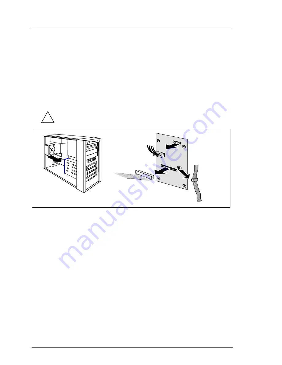
Replacing the SCSI backplane

The SCSI backplane is mounted on the hard disk cage. It is not necessary to 
remove the hard disk cage before replacing the SCSI backplane.

Requirements

server has been switched off

power cords have been disconnected

left side cover has been removed

all SCSI hard disk drives have been removed

  Check if all hard disk drives are uniquely identified so that you can 

reinsert them into their original bays.

Ê

Disconnect the power cable (1), the SCSI data cable (2), and the I

2

connector (3) from the SCSI backplane.

Ê

Remove the four screws (two at each side) that fasten the SCSI backplane 
holder to the hard disk cage.

Ê

Take the SCSI backplane together with the holder out of the server. Be 
carefully with the isolation foil.

Ê

Press down the rear side of the body-bound rivets which fasten the SCSI 
backplane to the holder and lift the SCSI backplane from the holder.

Installation of the new SCSI backplane is performed in reverse order.

!

1

2

3

1

Summary of Contents for PRIMERGY TX150 S2

Page 1: ...cting the server to the line voltage 02 TX150S2 26 Initial operation and operating 02 TX150S2 28 Unlocking locking the floorstand model 02 TX150S2 29 Controls and indicators on the front panel 02 TX150S2 31 Indicators on the rear 02 TX150S2 35 Switching the server on and off 02 TX150S2 37 Configuration of the server 02 TX150S2 39 SCSI RAID controller configuration 02 TX150S2 39 SATA RAID controlle...

Page 2: ...iew 02 TX150S2 65 Diagnostics 02 TX150S2 67 Assignment of the components in ServerView 02 TX150S2 67 Troubleshooting 02 TX150S2 69 Removal installation routines 02 TX150S2 75 Preparation 02 TX150S2 75 Opening closing the server 02 TX150S2 76 Floorstand model 02 TX150S2 76 Removing installing the drive covers 02 TX150S2 76 Removing installing the front cover 02 TX150S2 80 Rack model 02 TX150S2 81 H...

Page 3: ...eView service board S2 02 TX150S2 102 Boards in PCI slots 02 TX150S2 103 Installing removing a board 02 TX150S2 103 Removing the card guide 02 TX150S2 106 System board 02 TX150S2 107 Air duct 02 TX150S2 107 Removing installing the air duct 02 TX150S2 107 Main memory 02 TX150S2 108 Installing removing memory modules 02 TX150S2 109 Processor 02 TX150S2 111 Installing removing processor 02 TX150S2 11...

Page 4: ...ousing model 02 TX150S2 135 From floorstand model to rack model 02 TX150S2 135 Fit assembly kit and rack mount the server 02 TX150S2 141 Rack installation 02 TX150S2 141 Overviews lists 02 TX150S2 157 Spare parts 02 TX150S2 157 Glossary 02 TX150S2 157 Index 02 TX150S2 161 ...

Page 5: ...safety and avail ability through highly developed hardware and software components Hardware components include hot plugable hard disk modules optional hot plugable power supply modules ServerView server management Prefailure Detection and Analysing PDA and Automatic Server Reconfiguration and Restart ASR R Security functions in the BIOS Setup and on the system board protect the data on the server ...

Page 6: ... with 32bit 33 MHz 2 PCI slots with 64bit 66MHz Intel 82547GI Gigabit Ethernet controller with 10 100 1000 Mbit s Intel Kenai II Memory supported by South Bridge 6300ESB ICH 2 x UltraDMA100 connectors Video controller ATI Rage XL VGA onboard with 8 Mbyte SDRAM memory 2 fast IDE ATA controller onboard 2x ATA 100 LSI 1020 SCSI bus controller 2 USB 1 0 UHCI ontroller 1 USB 2 0 EHCI ontroller 4Mbit BI...

Page 7: ...ller a PCI standard SCSI controller or by a SCSI RAID controller In the SCSI version it is possible to install a HDD extension box in two bays of the accessible drives By this three additional ULTRA 320 SCSI hard disk modules can be used Only if the server is equipped with a RAID controller a defective hard disk module can be replaced during operation hot plug SATA version The hard disk subsystem ...

Page 8: ...ule of the redundant power supply unit fails the second power supply module ensures unimpaired continued operation and the defective power supply module can be replaced during operation hot plug High level of availability and failure protection When accessing stored data 1 bit errors in the main memory are automatically recognized and corrected by ECC mechanism ECC Error Detection Code ASR R Autom...

Page 9: ...ring Further information on the ServerView server management is provided in the associated documentation ServerStart You can configure the PRIMERGY server quickly and purposefully with the ServerStart software provided User guided menus are available for installing the server operating systems Service and Support PRIMERGY servers are service friendly and modular thus enabling quick and simple main...

Page 10: ...cessor 3 0 GHz 800 MHz 512 KB cache 2x 512 MB memory S26361 K934 V125 Floorstand model with Pentium 4 processor 3 0 GHz 800 MHz 512 KB cache 2x 1 GB memory S26361 K934 V107 Floorstand model with Pentium 4 processor 3 0 GHz 800 MHz 1 M cache 2x 256 MB memory S26361 K934 V117 Floorstand model with Pentium 4 processor 3 0 GHz 800 MHz 1 M cache 2x 512 MB memory S26361 K934 V127 Floorstand model with P...

Page 11: ...K934 V231 Floorstand model with Celeron processor 2 8 GHz 400 MHz 128 KB cache 1x 256 MB memory S26361 K934 V241 Floorstand model with Celeron processor 2 8 GHz 400 MHz 128 KB cache 1x 512 MB memory S26361 K934 V251 Floorstand model with Celeron processor 2 8 GHz 400 MHz 128 KB cache 1x 1 GB memory S26361 K934 V205 Floorstand model with Pentium 4 processor 3 0 GHz 800 MHz 512 KB cache 2x 256 MB me...

Page 12: ...0 MHz 1 M cache 2x 256 MB memory S26361 K934 V417 Rack model with Pentium 4 processor 3 0 GHz 800 MHz 1 M cache 2x 512 MB memory S26361 K934 V427 Rack model with Pentium 4 processor 3 0 GHz 800 MHz 1 M cache 2x 1 GB memory S26361 K934 V408 Rack model with Pentium 4 processor 3 2 GHz 800 MHz 1 M cache 2x 256 MB memory S26361 K934 V418 Rack model with Pentium 4 processor 3 2 GHz 800 MHz 1 M cache 2x...

Page 13: ...e slots accept 256 MB 512 GB or 1 GB DDR RAM modules The maximum main memory capacity is 4 GB Single channel and dual channel configuration are possible Single channel S26361 F3019 E512 Main memory 256 MB DDR I 400 occupies one bank max 2 or 3 per system S26361 F3019 E513 Main memory 512 MB DDR I 400 occupies one bank max 2 or 3 per system S26361 F3019 E514 Main memory 1 GB DDR I 400 occupies one ...

Page 14: ...em S26361 F3080 E1 CD RW DVD drive maximum 2 system S26361 F2573 E3 Tape drive LTO Ultrium 100 GB 7 5 MB s U2W SCSI maximum 2 system S26361 F2849 E3 Tape drive VXA 2 80 GB 6 MB s U2W SCSI maximum 2 system S26361 F2238 E3 Tape drive SLR 100 50 GB 5 MB s U2W SCSI max 2 system S26361 F2848 E3 Tape drive DDS4 Gen5 36 GB 3 MB s U2W SCSI maximum 2 system S26361 F2233 E3 Tape drive DAT DDS4 20 GB 2 8 MB ...

Page 15: ...4 or 7 system S26361 F2764 E173 73 GB 10000 rpm U320 SCSI 320 MB s max 4 or 7 system S26361 F2764 E114 146 GB 10000 rpm U320 SCSI 320 MB s max 4 or 7 system S26361 F2764 E518 18 GB 15000 rpm U320 SCSI 320 MB s max 4 or 7 system S26361 F2764 E536 36 GB 15000 rpm U320 SCSI 320 MB s max 4 or 7 system S26361 F2764 E573 73 GB 15000 rpm U320 SCSI 320 MB s max 4 or 7 system SATA version S26361 F3017 E80 ...

Page 16: ...r is written on the type label You need it if there is a HW error ServerView Version 3 5 RemoteView Version 3 1 ServerStart Version 5 405 ServerBooks Version 5 405 ServerSupport Version 5 405 Manufacturer Operating system Microsoft Windows 2000 Server SBS Windows 2003 Standard WEB Edition Windows SBS 2003 Standard Edition Novell NetWare 6 int l 6 5 Cluster Services 1 6 iSCSI Cluster Service 1 7 Su...

Page 17: ...100 V 240 V 1 9 A 0 8 A Max rated current 100 V 240 V 6 A 3 A Effective power 274 W Apparent power 300 VA Heat emission 986 kJ h Building fuse 16 A Protection class I Product safety IEC 60950 EN 60950 UL 60950 3rd Ed CAN CSA 22 2 No 60950 3rd Ed Electromagnetic compatibility FCC class A VCCI class A AS NZS 3548 class A CNS 13438 Interference emission Harmonic current Flicker EN 55022 class A EN 61...

Page 18: ...s Condensation in operating must be avoided Noise level Dimensions Floorstand model Rack model Width 205 mm 482 mm front panel Depth 605 mm 642 mm with handles Mounting depth 607 mm Height 444 mm with feet 221 mm or 5 HU Environment class 3K2 Environment class 2K2 DIN IEC 721 part 3 3 DIN IEC 721 part 3 2 Temperature Operating 3K2 Transport 2K2 10 C 35 C 25 C 60 C Humidity 10 85 Sound power level ...

Page 19: ...eration Installation Preparation Unpacking the server Do not unpack the server until it is at its installation location Ask somebody for help with carrying the server Should you discover that the delivery has damages incurred during transport or does not correspond to the delivery note notify your supplier immediately Ê Unpack all parts Ê Carry the server to its installation location ...

Page 20: ...peration Mounting the anti tilt bracket For floorstand models with redundant power supply the supplied anti tilt bracket must be fitted at the rear of the server Ê Position the server on the anti tilt bracket so the rubber feet of the server fit into the openings of the bracket 1 1 1 ...

Page 21: ... Installation Siemens Nixdorf Informationssysteme AG 1995 Pfad P 02 systemeinheiten TX150S2 TX150S2 e TX150S2 e k02 Ê Fasten the anti tilt bracket using the two knurled screws 1 Transportation locks Ê If the hard disk modules are equipped with transportation locks 1 remove them 1 ...

Page 22: ... the server to the line voltage Routing cables Installation steps rack model Mount assembly kit and insert server see order lists for location diagram prepared with Rack Architect see beginning page 02 TX150S2 141 Connect the devices to the server in accordance with the rack configuration Connecting the server to the line voltage Routing cables Preparing the keyboard Ê Plug the appropriate connect...

Page 23: ...S2 e TX150S2 e k02 Installing the hard disk cover You will find the hard disk cover in a seperate cardboard box Ê Unlock the server 1 and remove the key Ê Slide up the cover of the accessible drives as far as possible 2 Ê Hook the tabs of the hard disk cover into the recesses 3 and push the top end of the hard disk cover 4 in direction of the arrow until it engages 2 1 3 3 4 ...

Page 24: ...ur server depend on the PCI boards installed You will find an additional USB port on the front side of the server The standard ports are indicated by symbols and by color coding for the connectors Floorstand model 1 Mouse port green 6 Serial port COM2 turquoise 2 Parallel port burgundy 7 Serial port COM1 turquoise 3 LAN port 8 Keyboard port purple 4 Monitor port blue 9 LEDs 5 USB port 1 and 2 blac...

Page 25: ...device Ê Connect the data cables at the server and peripherals Connecting the monitor to the line voltage Ê Plug the power cord of the monitor into a properly grounded power outlet of the main AC supply circuit The rated current for the monitor can be found on the technical data label on the monitor 1 Mouse port green 6 Serial port COM2 turquoise 2 Parallel port burgundy 7 Serial port COM1 turquoi...

Page 26: ...e voltage range from 100 V 240 V It is not necessary to switch over the power supply unit Standard power supply Ê Plug the delivered power cord into the insulated socket of the server 1 and into a properly grounded power outlet of the main AC supply circuit and or the rack model into the socket strip of the rack 2 see also item rack in the service manual module System components 1 2 ...

Page 27: ...150S2 TX150S2 e TX150S2 e k02 Redundant power supply Ê Connect each power supply module to a grounded power outlet with the power cable supplied 1 2 You will find the description of the indicatorsof the power supply module on page 02 TX150S2 36 If you connect the two power cords to seperate power circuits you can operate the unit with power phase redundancy 2 2 1 1 ...

Page 28: ... Installation and initial operation Initial operation and operating The server must be acclimatized in its operating environment for an acclimatization time Temperature difference C operating environment outside Minimum acclimatization time hours 5 3 10 5 15 7 20 8 25 9 30 10 ...

Page 29: ...S2 e k02 Unlocking locking the floorstand model For opening and closing of the server you need the delivered key Ê Turn the key 90 clockwise 1 Ê Slide the cover of the accessible drives downwards 2 Ê If you wish to prevent access to the hard disk modules then lock the server again 3 Now the cover of the accessible drives cannot be slid into the top position and the hard disk cover cannot be remove...

Page 30: ...ration Enabling access to the hard disk modules Ê Unlock the server 1 Ê Remove the key Ê Slide up the cover of the accessible drives as far as possible 2 Ê Remove the hard disk cover toward the front 3 4 The reinstalling of the hard disk cover and the locking of the server is done in reverse order 1 2 4 3 ...

Page 31: ...ols and indicators on the front panel 1 ON OFF button 8 ID indicator 2 Operating status indicator standby 9 USB connector 3 Indicator hard disk drive busy 10 Indicators hard disk drive 4 Global Error indicator 11 Indicator floppy disk drive 5 NMI button 12 Indicator CD ROM DVD drive CD burner 6 Reset button 13 Lock only for floorstand model 7 ID button ID identification reset 6 NMI 5 4 3 2 1 10 11...

Page 32: ...utton starts an non maskable interrupt The NMI button can only be activated with a pointed object eg bent paperclip reset Reset button Pressing the reset button restarts the System via BIOS The reset button can only be activated with a pointed object eg bent paperclip ID ID button localize Pressing the ID button lights up the integrated ID indicator on the front and the ID indicator on the rear si...

Page 33: ...ent has occurred Blinks orange when a critical event has occurred or a pre failure event has been detected Users can check BIOS setup system and event log for event details or use ServerView The indicator blinks also in standby mode Lights orange when a prefailure event has been detected Users can check system and event log for event details or use ServerView The indicator lights also in standby m...

Page 34: ...ge HDD Faulty oder Rebuild Stopped drive defective needs replacing a rebuild process was stopped or the HDD module is not correctly inserted slow blink HDD Rebuild a rebuild is carried out by the RAID controller after replacing a hard disk drive fast blink HDD Identify four fast blinks pause HDD Predicted Fault not relevant for the Promise TX4 SATA RAID controller two fast blinks pause HDD hot spa...

Page 35: ...for event details or use ServerView The indicator blinks also in standby mode Lights orange when a prefailure event has been detected Users can check system and event log for event details or use ServerView The indicator lights also in standby mode After power off the indicator is activated after a reload if the event is still critical 2 ID indicator blue Pressing the ID button lights up the integ...

Page 36: ...supply modules 1 AC OK indicator green 2 FAIL indicator amber 3 Power Good indicator green AC OK FAIL Power Good Meaning Off Off Off No AC power to all power supply modules or no AC power to this power supply module only On Off Blinking AC present standby output on On Off On Power supply DC outputs on and ok On On Off Power supply failure 1 2 3 ...

Page 37: ... device First system installation Insert the ServerStart CD and any available floppy configuration disk and restart the device Make the configuration of the Server with ServerStart Operating system already installed The server is switched on performs a system test and boots the operating system Please note that the memory size displayed during the system test varies according to the PCI slot equip...

Page 38: ...the server will be switched on or off Modem signal ring indicator The server is switched ON via an internal or external modem Wake On LAN WOL The server is switched ON by a command via the LAN Magic Package After a power failure The server automatically switches ON following a power failure depending of the settings in the BIOS Power button override function You can switch off the system by pressi...

Page 39: ...ler is either performed via the BIOS configu ration utility calling CTRL C during BIOS POST or with the ServerStart CD using GAM Global Array Management You will find further information in the controller documentation on the ServerBooks CD in section controllers SCSI ID information Please note that the SCSI IDs for the hard disk modules are predefined see page 02 TX150S2 63 Activating the hard di...

Page 40: ...ServerBooks CD in section controllers Activating the hard disk write cache By default the hard disk write cache is disabled This presetting may be changed Consequently not every data modification in main memory is written to disk immediately thus boosting system performance during write operations When a power failure occurs with enabled write cache data may be lost The hard disk write cache shoul...

Page 41: ...onfiguration with the GAM Global Array Manager SATA hard disks The menu guided configuration includes the server configuration with the SCU and the SATA RAID controller configuration with the PAM Promise Array Manager To find out how to operate ServerStart and for further information refer to the corresponding ServerStart manual Configuration without ServerStart Configuring the SCSI RAID controlle...

Page 42: ...nitoring and diagnostics system RemoteView automatically you have to enter the disk parameters in the BIOS setup and boot one time from the RemoteView medium chipDISK You find the description how to proceed under Configuring the chipDISK on page 02 TX150S2 101 For more details on the operation of RemoteView please refer to module Diagnostics of the service manual ...

Page 43: ... e TX150S2 e k02 Settings System board D1751 Interfaces and connectors No Print Connector 1 PC98 Power control connector PS connector P9 2 ATX 12 V1 CPU power supply ATX 12V PS connector P8 3 CPU_FAN1 Processor fan 13 15 16 14 9 6 5 4 3 2 1 8 10 11 7 12 DIMM_1B PCI slot 5 DIMM_0B PCI slot 4 PCI slot 1 PCI slot 2 PCI slot 3 DIMM_1A DIMM_0A 18 1 1 1 17 DIMM0 DIMM1 DIMM2 DIMM3 ...

Page 44: ...or accessible drives 10 Intrusion Intrusion detection 11 USB3 4 USB connector for front side USB 12 Buzzer1 Onboard speaker 13 Frontpanel Connector for operating panel board 14 RSB LP Power Not used 15 IPMB1 RSBS2 data 16 RSB Power Not used 17 HD ACTIVITY HD LED connector for RAID controller 18 CHA_FAN1 System fan 1 PS 2 mouse port 5 Serial port 2 COM2 2 PS 2 keyboard port 6 LAN port onboard 3 Ser...

Page 45: ...smission and receiving buffer FIFO and supports WOL function through Magic PacketTM It is also possible to boot a device without its own boot hard disk via LAN Here Intel PXE is supported The LAN RJ45 connector is equipped with a yellow and a green LED light emitting diode This LEDs are integrated into the LAN connector socket LED 1 left LED 2 right 1 Green indicator 2 Yellow green indicator LNK L...

Page 46: ...asurement of the processor temperature measurement of the system temperature with two onboard temperature sensors measurement of the ambient temperature with an external temperature sensor Fan monitoring Fans that are no longer available blocked or sticking fans are detected Sensor monitoring The removal of or a fault in a temperature sensor is detected Should this happen all fans monitored by thi...

Page 47: ... resources PCI slots Device IRQ Address DMA Keyboard 1 060 064 Serial port COM2 3 03F8 02F8 03E8 02E8 Serial port COM1 4 03F8 02F8 03E8 02E8 5 Floppy disk drive controller 6 03F0 3F5 3F7 2 Parallel port LPT1 7 0278 0378 03BC 0 1 3 Real time clock RTC 8 070 071 free 9 10 11 Mouse controller 12 Numeric processor 13 0F0 0FE IDE controller 14 1F0 1F7 free 15 PCI slot 64 bit 32 bit Bus frequency Descri...

Page 48: ...rrupt INTA per PCI slot The PCI interrupts INTA INTB INTC and INTD are available for every PCI slot The same interrupt can be assigned simultaneously to several PCI boards You should avoid this condition due to reduced performance If you use a setting other than Auto the Plug Play functionality of the system BIOS for the corresponding PCI boards is deactivated Auto The PCI interrupts are assigned ...

Page 49: ...ontroller Interrupts of SCSI channel A respektive B LAN interrupts are not PCI specific onboard SATA controller if installed A B C D E F G H PXIRQ0 PXIRQ1 PXIRQ2 PXIRQ3 Slot 1 A B C D Slot 2 C D A B Slot 3 B C D A Slot 4 D A B C Slot 5 C D A B USB controller HC0 A USB controller HC1 A USB 2 0 controller A LAN controller A VGA controller A Promise controller A SCSI controller A IDE controller P ATA...

Page 50: ...ou are using an external graphic controller you will find details of supported screen resolutions in the Operating Manual or Technical Manual supplied with the controller Processor s clock speed The clock frequency of the processor is set automatically It cannot be changed manually Screen resolution Refresh rate Hz Maximum number of colors 640x480 200 16 7 Mio 800x600 200 16 7 Mio 1024x768 150 16 ...

Page 51: ...Ds No Jumper Function 1 BIOSREC This jumper enables recovery of the old system BIOS after an attempt to update has failed 1 2 2 3 default the system starts with the BIOS from the system board the system starts from the Flash BIOS diskette in drive A and allows a BIOS recovery 4 3 2 1 A DIMM_1B PCI slot 5 DIMM_0B PCI slot 4 PCI slot 1 PCI slot 2 PCI slot 3 DIMM_1A DIMM_0A 1 1 1 DIMM0 DIMM1 DIMM2 DI...

Page 52: ...e LSI 1020 64 bit PCI X SCSI controller 1 2 2 3 default The LSI 1020 64 bit PCI X SCSI controller has been activated The LSI 1020 64 bit PCI X SCSI controller has been deacti vated 4 KBPWR1 This jumper allows you to chose the operating voltage of the keyboard 1 2 2 3 default 5V 5V stand by No LED Description A LED1 On Flashes Initialisation of the BMC after voltage is available duration 10 15 seco...

Page 53: ...with or without accu pack use slot PCI slot 1 4 or 5 You find the slot sequence for main memory on page 02 TX150S2 108 1 Locations for main memory 5 PCI slot 32bit 33MHz 2 Lithium battery 3V 5 Lithium battery 3V 3 PCI slot 64bit 66MHz 7 PCI slots 32bit 33MHz 4 PCI slot 64bit 66MHz ZCR 7 6 2 1 DIMM_1B PCI slot 5 DIMM_0B PCI slot 4 PCI slot 1 PCI slot 2 PCI slot 3 DIMM_1A DIMM_0A 1 1 1 DIMM0 DIMM1 D...

Page 54: ...sk in the PRIMERGY TX150S2 server the jumper is set from MA to CS 1 Jumper block CS Cable detected Mode Assignment depends on other devices on this data line SL Slave Mode second device on this data line MA Master Mode first device on this data line The system is delivered with the jumper set for master mode 2 Compactflash card 3 Connector for the power supply 4 Connector for the data lines CS SL ...

Page 55: ...s Nixdorf Informationssysteme AG 1995 Pfad P 02 systemeinheiten TX150S2 TX150S2 e TX150S2 e k02 Operating panel board Part number A3C40050401 The operating panel board is included in the spare part operating panel module C26361 K644 Z330 1 Connector for operating panel cable 2 USB connector 1 2 i ...

Page 56: ...k modules on the hard disk cage The termination is done by the SCSI backplane The LEDs are made visible at the front side of the mounting frames via light conductors which are situated at the mounting frames of the drives 1 X5 SCSI input connector 4 LEDs 2 X6 Power connector 5 SCA connectors ID0 upto ID3 3 X7 SMB connector i C bus 1 5 SCSI ID 2 SCSI ID 1 SCSI ID 0 2 4 SCSI ID3 3 ...

Page 57: ...e The LEDs are made visible on the front side of the mounting frames via light conductors which are situated at the mounting frames of the drives The signal of the LEDs is the same as for SCSI hard disk drives The controlling of the LEDs does only work if a driver has been loaded 1 I2C bus connector X11 5 not used Program connector 2 SMB connector I2 C bus X10 6 LEDs 3 Jumper FW Run X13 jumper is ...

Page 58: ...02 TX150S2 58 July2004 U41057 J19 Z146 1 76 Settings Installation and initial operation Power backplane Part number A3C40052762 1 Connector power supply module 1 2 Connector power supply module 2 1 2 ...

Page 59: ...d the four internal hard disk drives are connected to the onboard SCSI controller via one SCSI cable The HostRAID function can also be used with this cabling 1 channel SCSI version with additional SCSI RAID controller A SCSI RAID controller is installed into a PCI slot and connected with the four internal hard disk drives In this case the connection to the onboard SCSI controller must be changed t...

Page 60: ...switch SCSI HD ID3 SCSI HD ID2 SCSI HD ID1 SCSI HD ID0 1 HDD System fan Y1737 V111 Y3785 V301 chipDISK Y1548 V9 Y1548 V10 opt Legend SCSI IDE FD Data SCSI backplane 1 channel Y1248 V8 ID Temp Combo X7 Y3736 V1 USB X6 X5 Cable prefix T26139 On Off SW Stdby Power LED HD Active LED Identify LED Global Error LED Reset SW NMI SW Y3728 V1 USB PSU P8 D1751 partition P9 P1 Y3718 V508 Y3904 V1 Y3912 V1 CHA...

Page 61: ... Intrusion switch Intrusion switch SCSI HD ID3 SCSI HD ID2 SCSI HD ID1 SCSI HD ID0 1 HDD System fan Y1737 V111 chipDISK Y1548 V9 Y1548 V10 opt Legend SCSI IDE FD Data SCSI backplane 1 channel Y1248 V8 ID Temp Combo X7 Y3736 V1 USB X6 X5 Cable prefix T26139 On Off SW Stdby Power LED HD Active LED Identify LED Global Error LED Reset SW NMI SW Y3728 V1 USB PSU P8 D1751 partition P9 P1 Y3718 V508 Y390...

Page 62: ...ration Cabling HDD extension box CD Rom Floppy SCSI HD ID3 SCSI HD ID2 SCSI HD ID1 SCSI HD ID0 1 HDD chipDISK opt ID Temp Combo X7 X6 X5 PSU D1751 partition Y3718 V508 P2 P3 HDD extension box RAID contr Y3927 V1 SCSI backplane 1 channel Legend SCSI IDE FD Data USB Power Cable prefix T26139 ...

Page 63: ... and other drives must have an unambigous address The address is called ID identifier When connecting drives make sure that no ID is assigned more than once On the SCA hard disks the IDs needn t to be set For each hard disk bay a corresponding ID is determined by hardware SCSI backplane It is not possible to change this IDs SCSI addresses with HDD extension box SCSI backplane Hard disk ID3 Hard di...

Page 64: ...DISK Y1548 V9 Y1548 V10 opt Legend SCSI IDE FD Data Y1248 V8 ID Temp Combo USB Cable prefix T26139 On Off SW Stdby Power LED HD Active LED Identify LED Global Error LED Reset SW NMI SW Y3728 V1 USB PSU P8 D1751 partition P9 P1 Y3718 V508 Y3904 V1 Y3912 V1 CHA FAN1 P5 P4 P2 P3 P7 P6 Power HD ACTIVITY Y2361 V102 Y3576 V209 SATA SATA controller Port 4 2 1 3 4x Y3928 V1 SATA HD ID3 SATA HD ID2 SATA HD...

Page 65: ...on cable Connecting intrusion switches to system board Intrusion T26139 Y3728 V1 Fan adapter cable Connecting system fan to system board CHA_FAN1 T26139 Y1248 V8 Floppy disk cable Connecting floppy disk drive to system board Floppy T26139 Y1737 V111 ATAPI CDROM cable Connecting ATAPI CDROM to IDE1 port on system board PRI_IDE T26139 Y3785 V301 SCSI cable Connecting internal SCSI drives acces sible...

Page 66: ...n SATA controller Option add on controller signalize T26139 Y2361 V102 Signal cable Connecting controller to system board HD ACTIVITY signalizing HDD access to front panel Option HDD extension box T26139 Y3927 V1 SCSI cable Connecting HDD extension box to controller Option chipDISK T26139 Y1584 V9or T26139 Y1584 V10 IDE cable chipDISK Connecting chipDISK to IDE port on system board SEC_IDE Option ...

Page 67: ...Description 0 FAN CPU CPU fan speed can be controlled 1 FAN STD PSU Fan standard power supply 2 FAN SYS System fan speed can be controlled No Purpose Description 0 FAN CPU CPU fan speed can be controlled 1 FAN SYS System fan speed can be controlled 2 FAN RED PSU0 Fan 1 of the first power supply module 3 FAN RED PSU0 Fan 2 of the first power supply module 4 FAN RED PSU1 Fan 1 of the second power su...

Page 68: ... Assignment of the components in ServerView Diagnostics Power supply units No Purpose Description 0 PSU0 Slot 0 standard power supply or redundant power supply first module 1 PSU1 Slot 1 redundant power supply second module optional PSU 0 PSU 1 ...

Page 69: ...he server Ê Wait a few seconds and plug the power plug into the grounded power outlet again Ê Switch on the server Server switches itself off Server Management has detected an error Ê If it is possible to restart the server so that ServerView can be used check the error list in the program ServerView or the ErrorLog file and try to correct the detected error Screen remains dark Monitor is switched...

Page 70: ...or Further information about the horizontal frequency also called line frequency or horizontal deflection frequency can be found in the operating manual concerning the monitor Ê How to set the correct horizontal frequency of the monitor can be looked up in the manual concerning the software of the graphics card or the manual concerning the operating system No screen display or drifting screen disp...

Page 71: ...OS Setup if the mouse controller is enabled Floppy disk cannot be read or written Ê Check if the write protection of the floppy disk is activated Ê Check the entry for the floppy disk drive in the BIOS Setup Ê Check in the BIOS Setup if the floppy disk drive controller and the write permission are switched on information can also be found in the technical manual for the system board Ê Make sure th...

Page 72: ... on the SATA RAID controller Promise Array Management PAM for FastTrak S150 TX2plus S150 TX4 and TX4000 User Manual System will not boot after installing a new hard disk drive only SCSI version SCSI configuration incorrect ultra wide SCSI controller Ê Check in the SCSI configuration menu the settings for the hard disk drives SCSI Device Configuration and the additional settings Advanced Configurat...

Page 73: ...on providing the server has a RAID controller RAID controller is not configured for this hard disk drive The drive was installed with the system switched Off Ê Reconfigure the RAID controller for the drive with the corresponding utility You will find the Information in the documentation of the RAID controller or Ê Re insert the hard disk module with the system switched on into a free bay Further i...

Page 74: ...02 TX150S2 74 July2004 U41057 J19 Z146 1 76 Troubleshooting Diagnostics ...

Page 75: ... components Observe that electrostatic sensitive devices ESDs should only be held at the edges and placed on a pad which is free from electrostatic charge Any devices or tools that are used must be free from electrostatic charge For this purpose wear an electrostatic wrist band or use a suitable grounding cable that connects you to the external chassis of the system unit Procedures which are ident...

Page 76: ...r Floorstand model If you want to fully open the server you must proceed as follows remove the drive covers remove the left side cover remove the front cover Removing installing the drive covers There are two drive covers hard disk cover cover of the accessible drives front sliding cover upper position Hard disk cover 1 2 4 3 ...

Page 77: ... far as possible 2 Ê Remove the hard disk cover towards the front 3 4 Mounting of the hard disk cover is performed in reverse order Cover of the accessible drives The cover for the accessible drives is held in place in the indicated guides by two tabs on the right and left To provide a better understanding of the procedure the installation is described before the removal Installing Ê Hook the tabs...

Page 78: ...he server Removal installation routines Ê Push backwards the top end of the cover of the accessible drives 1 Ê Now you can slide the cover of the accessible drives up and down 2 Removing Ê Slide the cover of the accessible drives to the position marked 1 1 2 1 2 ...

Page 79: ...Pull forwards the top end of the cover of the accessible drives and remove it 2 When you remove the cover make sure that the both guide notches topside are not damaged Removing Installing the left side cover Ê Unlock the server 1 Ê Remove the two screws 2 at the rear Ê Push back the left side cover in the direction marked 3 Ê Remove the left side cover 4 Installation is performed in reverse order ...

Page 80: ...sengage the three tabs 1 on the left side one after the other and rotate the front cover outwards 2 about 2 cm Ê Disengage the two tabs 1 on the right side one after the other and pull out the front cover frontwards 2 Installation of the front cover is performed in reverse order For installing make sure that all tabs engage correctly 1 2 1 2 ...

Page 81: ...iemens Nixdorf Informationssysteme AG 1995 Pfad P 02 systemeinheiten TX150S2 TX150S2 e TX150S2 e k04 Rack model Ê Loosen the four knurled screws 1 and pull the server carefully out of the rack up to the stop 2 Ê Press in the locking spring 1 on both sides and carefully pull the server outwards 2 1 2 1 2 ...

Page 82: ...val installation routines You need the help of another person to take the server out of the rack Ê Remove the telescopic rails on the left and right side three screws Ê Take the server out of the rack Ê Unlock the top cover with removing the two screws at the rear 1 2 2 3 1 2 ...

Page 83: ...he hard disk Each module is equipped with a status indicator and an error indicator The hard disk subsystem can be controlled by the onboard U320 controller a PCI standard SCSI controller or by a SCSI RAID controller The SCSI IDs of the hard disk modules are predefined see also page 02 TX150S2 63 In the SCSI version it is possible to install a HDD extension box in two bays of the accessible drives...

Page 84: ...r in the RAID controller manual Notice the following for hard disk drives connected to a RAID controller RAID level 0 and 7 Rebuild is not possible If a hard disk fails its data is lost RAID level 1 and 5 without standby hard disk Rebuild on the new disk is carried out automatically when the old disk is replaced RAID level 1 and 5 with standby hard disk A standby hard disk is automatically activat...

Page 85: ...or lights up when a hard disk drive is being accessed The hard disk module cannot be replaced at this time Orange indicator The orange LED flashes when in conjunction with a RAID controller the configuration is being determined or a rebuild is being done You may not replace the hard disk module at this time The orange LED remains lit if the hard disk drive is deacti vated and or defective and can ...

Page 86: ...s for labeling are also provided The stickers are color coded for an easier identifi cation If a hard disk module is to be installed in a bay in which no hard disk module was previously installed then the dummy cover must be removed from this bay beforehand Removing the dummy cover Ê Press the two locking tabs at the left and right on the dummy cover together 1 until the detent is released Ê Remov...

Page 87: ...S2 TX150S2 e TX150S2 e k04 Installing the dummy cover Ê Insert the dummy cover into the empty bay Make sure that the dummy cover engages properly in the bay on each side Installing SCSI hard disk module Ê Solve the locking mechanism 1 by pressing the locking button Ê Swing the handle of the hard disk module fully upwards 2 Ê Insert the new hard disk module 1 i 1 2 2 1 1 ...

Page 88: ...n if you are not sure that the hard disk drive is operated on a RAID controller and is part of a disk array operates in RAID Level 1 or 5 If you replace a hard disk module during operation proceed as follows Ê Solve the locking mechanism of the hard disk module indicated as defective by pressing the locking button Ê Swing the handle of the hard disk module fully upwards Ê Pull out the hard disk mo...

Page 89: ...disk drive need to be changed out of its carrier Make sure that the new hard disk drive has the right interface SCA or SATA Ê Remove the hard disk module indicated as defective Ê Remove the four screws on the sides of the hard disk carrier two on the right and two on the left Ê Take the hard disk drive out of the hard disk carrier Ê Replace the hard disk drive or the hard disk carrier Ê Mount the ...

Page 90: ...l hard disk drives are uniquely identified so that you can reinsert them into their original bays Ê Disconnect the power cable 1 the SCSI data cable 2 and the I2 C connector 3 from the SCSI backplane Ê Remove the four screws two at each side that fasten the SCSI backplane holder to the hard disk cage Ê Take the SCSI backplane together with the holder out of the server Be carefully with the isolati...

Page 91: ... hard disk drives have been removed Check if all hard disk drives are uniquely identified so that you can reinsert them into their original bays Ê Disconnect the power cable 1 the four SATA data cables 2 and the I2C connector 3 from the SCSI backplane Ê Remove the four screws two at each side that fasten the SATA backplane holder to the hard disk cage Ê Take the SATA backplane together with the ho...

Page 92: ...ating panel module also in the drive cage for accessible drives Installing removing an accessible 5 25 drive Requirements server has been switched off power cords have been disconnected left side cover has been removed front cover has been removed New 5 25 drive are delivered without EasyClick rails Before installing a new 5 25 drive you have to unscrew the EasyClick rails from the dummy cover or ...

Page 93: ...ve the EasyClick rails from the dummy cover by removing the four screws 2xUNC6 32 and 2xM3 on each side Keep the dummy cover for future use In case the 5 25 drive is later removed and not replaced by a new one the dummy cover has to be reinstalled to comply with applicable EMC regulations regulations on electromagnetic compatibility and satisfy cooling requirements and fire protection measures Ins...

Page 94: ...installed Ê Push the accessible drive into the bay until the locking mechanism of the EasyClick rails engages Ê Connect one end of the IDE SCSI flat ribbon cable to the IDE connector of the accessible drive Ê Connect the power plug to the power connector of the accessible drive Removing an accessible 5 25 drive Ê Disconnect the SCSI IDE data cables and the power supply cable from the accessible dr...

Page 95: ...backplane without cables via the SCA interface This allows SCSI hard disk modules to be simply plugged in or pulled out If the server has a RAID controller and a corresponding RAID configuration defective hard disk modules can also be exchanged during operation For upgrading to a HDD extension box you need the conversion kit S26361 F2826 E1 Requirements server has been switched off power cords hav...

Page 96: ...bay Ê Connect the power plug P2 to the power connector of the HDD extension box see cabling on page 02 TX150S2 62 Ê Connect the I C bus cable with the I C bus connector of the HDD extension box Ê Connect the SCSI cable T26139 Y3927 V1 included in the conversion kit to the SCSI connector on the HDD extension box Ê Route the SCSI cable and connect it to the SCSI connector on the 1 or 2 channel RAID ...

Page 97: ...nnect all cables from the HDD extension box Ê Pull the HDD extension box completely out of its bay Ê Remove the EasyClick rails from the HDD extension box by removing the four screws on each side Replacing the operating panel board Requirements server has been switched off power cords have been disconnected left side cover has been removed front cover has been removed Ê Press together the two spri...

Page 98: ...t is possible to have access to the cable tie Ê Thread the two cables through the cable tie Ê Push the operating panel module into its bay as far as it is possible to plug the cables Ê Plug the flat ribbon cable and the USB cable on the operating panel board Ê Push the operating panel module into the housing until it engages Replacing the floppy disk drive Requirements server has been switched off...

Page 99: ...ormationssysteme AG 1995 Pfad P 02 systemeinheiten TX150S2 TX150S2 e TX150S2 e k04 Ê Remove the two screws 1 that attach the drive holder to the housing front side Ê Pull the drive holder out of the server 2 Ê Remove the two screws 1 and take the floppy disk drive out of the drive holder Installation is performed in reverse order 1 ...

Page 100: ...ifferent versions are available chipDISK with removable CompactFlash CF mass storage card chipDISK with removable Microdrive storage ranging from 170 MB to 1 GB CF compatible Installing removing the chipDISK Requirements server has been switched off power cords have been disconnected left side cover has been removed Ê Set the jumper from position MA to CS The positions MA and SL remain open Ê Conn...

Page 101: ... system board see page 02 TX150S2 59 The primary IDE channel remains hidden in the BIOS until a system failure activates the chipDISK Do not connect a second device to the primary IDE channel the chipDISK must occupy this channel alone You may however connect two devices master and slave to the secondary IDE channel Removal is performed in reverse order Configuring the chipDISK You must enter the ...

Page 102: ... and the RemoteView from the chipDISK If the RemoteView software is not yet installed on the chipDISK install the software as described in the manual for RemoteView Ê To terminate RemoteView use the menu item Boot Original OS The server will then boot the standard operating system RemoteView service board S2 You will find the installation removal and configuration of the RSB S2 in the item RSB S2 ...

Page 103: ...rd Installing removing a board Requirements server has been switched off power cords have been disconnected left side cover has been removed Installing a board Ê Press in direction of the arrow 1 on the clamp fix and remove it 2 Ê Take out the rear slot cover plate of the slot 3 Do not dispose of the rear slot cover plate For cooling protection against fire and in order to comply with EMC regulati...

Page 104: ...ove a Ê Insert the clamp fix for fastening the board as shown 2 Make sure that the clamp fix engages in the housing Ê If necessary plug the lines on the new board Removing a board Even with the system switched off certain parts of the device e g memory modules and PCI expansion boards may still be energised These components may only be replaced when the device is completely disconnected to the lin...

Page 105: ... TX150S2 e k04 Ê Press in direction of the arrow 1 on the clamp fix and remove it 2 Ê Pull out the board of the slot 3 Ê Insert the rear slot cover plate into the empty slot 1 Make sure that the rear slot cover plate is positioned in the groove a Ê Insert the climb fix for fastening the rear slot cover plate as shown 2 Make sure that the climb fix engages in the housing 2 1 3 a 1 2 ...

Page 106: ...h PCI boards mounted into the lower three slots You find the card guide above the SCSI hard disk cage Requirements server has been switched off power cords have been disconnected left side cover has been removed Ê Remove the full length PCI boards from the lowest PCI slots Ê Remove the screw see arrow Ê Take the card guide out of the server Mounting is performed in reverse order ...

Page 107: ...xdorf Informationssysteme AG 1995 Pfad P 02 systemeinheiten TX150S2 TX150S2 e TX150S2 e k04 System board Air duct Removing installing the air duct Ê Take out the air duct upwards Ê Reinstall the air duct Make sure that the system fan cable and the power supply cables fit into the recesses see circles ...

Page 108: ...are possible In the dual channel configuration you must install identical memory modules in DIMM 0A and 0B blue slots and identical memory modules in DIMM 1A and 1B black slots Mode DIMM 0A blue DIMM 1A black DIMM 0B blue DIMM 1B black 1x memory module S26361 F3019 E51x single channel populated 2x memory module S26361 F3019 E51x single channel populated populated 3x memory module S26361 F3019 E51x...

Page 109: ...ed left side cover has been removed air duct has been removed Installing memory modules Ê Flip the ejector tabs on each side of the relevant slot outwards Ê Insert the memory module into the slot 1 until the ejector tabs engage on both sides of the memory module 2 Removing memory modules Even with the system switched off certain parts of the device e g memory modules and PCI expansion boards may s...

Page 110: ...02 TX150S2 110 July2004 U41057 J19 Z146 1 76 System board Removal installation routines Ê Flip the ejector tabs on each side of the slot outwards 1 Ê Remove the memory module from its slot 2 1 1 2 ...

Page 111: ...e with the smooth side down Never slide a processor over a surface Installing removing processor Requirements server has been switched off power cords have been disconnected left side cover has been removed air duct has been removed Before removing the processor from its socket the heat sink with the processor fan must be removed Heat sink and processor fan are one unit and they are removed or ins...

Page 112: ...he heat sink has cooled before removing it Ê Unplug the processor fan cable from the connector on the system board Ê First unlock the retaining clip on one side see arrows by pressing it down then swivel it upwards and take the hook out of the other side see circle Ê Remove the retaining clip on the other side in the same way Ê Take the heat sink carefully out of the heat sink mounting ...

Page 113: ...g downwards The processor can only be installed in one direction in the socket Pay attention to the marking triangled golden colored on one of the corners for the correct alignment To avoid damaging the pins and the processor do not force the processor into the socket Ê Lock the processor in the socket by pushing the socket lever back in place Ê Clean the surface of the processor Preparing the hea...

Page 114: ...ive paste Installing the heat sink with the processor fan Never install a processor without a heat sink the processor can overheat and lead to failure of the processor and the system board Ê Put the prepared heat sink with the processor fan into the heat sink mounting Ê Hang up the retaining clip on one side of the heat sink mounting and then press it down on the other side Fix the heat sink with ...

Page 115: ...ionssysteme AG 1995 Pfad P 02 systemeinheiten TX150S2 TX150S2 e TX150S2 e k04 Ê Pass the processor fan cable through the retaining clip see arrow Ê Connect to processor fan cable to the connector CPU_FAN1 on the system board The clock frequency of the processor is set automatically It cannot be changed manually i ...

Page 116: ...ium battery must be replaced with an identical battery or with a battery type recommended by the manufacturer CR2032 Do not throw lithium batteries into the trashcan Please dispose of batteries in accordance with local government regulations Make sure that you insert the battery the right way round The plus pole must be on the top Ê Push the locking spring in the direction of the arrow 1 so that t...

Page 117: ... disconnected left side cover has been removed Ê Lay the floorstand model on a flat surface with the uncovered side facing upwards This step has to be carried out by two people as the server may weight up to 28 kg Ê Remove the memory modules Ê Remove all controllers from their slots Ê Remove the air duct Ê Remove the system fan Ê Remove the processor heat sink Ê Remove the processor Ê Remove all c...

Page 118: ...r side of the server Thereby you lift the system board out of the guide rings of the centre bolts Ê Push the system board 1 cm in the direction of the hard disk cage Proceeding this way the connectors and the two light emitting diodes are pulled out of the connector panel Ê Carefully remove the system board from the casing by grasping the PCI slots 1 Centre bolts 2 Centre bolts 2 1 ...

Page 119: ...system board with the two centre bolts 1 2 in graphic on page before Make sure that the guide rings engage properly in the drill holes of the system board After this it is no longer possible to push the system board sidewards Ê Fasten the system board with the 11 screws Ê Reconnect the cables to their original connectors For the cabling see page 02 TX150S2 59 Ê Reinstall the processor and the proc...

Page 120: ... is equipped with the standard power supply unit Standard power supply Replacing standard power supply unit Requirements server has been switched off power cords have been disconnected left side cover has been removed You can replace the power supply without removing the adapter sheet Ê Disconnect all cables of the power supply Take note of the cabling Ê Remove the four mounting screws of the powe...

Page 121: ...able layout of the power supply Redundant power supply The redundant power supply consists of up to two power supply modules To achieve power supply redundancy the installation of the second power supply module is required If one power supply module fails the other power supply module ensures unimpaired further operation The defective power supply module can be replaced during operation hot plug p...

Page 122: ...pply module in a non redundant configuration the second power supply module was not installed requires that the server has been switched off Ê Unplug the power cord from the connector of the power supply module Ê Push the locking slide upwards and pull the green handle frontwards Ê Pull the power supply module out of the installation bay ...

Page 123: ...temeinheiten TX150S2 TX150S2 e TX150S2 e k04 Ê Push the new power supply module into the installation bay Ê Lift the green handle somewhat upwards so that the forked levers see circles can fit to the noses see arrows Ê Push the green handle downwards until the locking slide engages Ê Plug the power cord to the connector of the power supply module ...

Page 124: ...per side see circle and take it out Do not dispose of the dummy module For cooling protection against fire and in order to comply with EMC regulations you must refit the dummy module if you remove the power supply module and no new power supply module will be installed Ê Push the new power supply module into the installation bay Ê Lift the green handle somewhat upwards so that the forked levers ca...

Page 125: ...es are unremovable connected to the power backplane Ê Lay the floorstand model on a flat surface with the uncovered side facing upwards This step has to be carried out by two people as the server may weight up to 28 kg Ê Remove the air duct Ê Disconnect all power cables of the redundant power supply For the cabling see page 02 TX150S2 59 Ê Remove the knurled screw see circle which fasten the power...

Page 126: ... one power supply module is installed you have to install the dummy module in the second bay several screws anti tilt bracket Requirements server has been switched off power cords have been disconnected left side cover has been removed air duct has been removed After installing the redundant power supply the SDR sensor data record data base must be updated For this sequence you need a BIOS flash d...

Page 127: ... 1995 Pfad P 02 systemeinheiten TX150S2 TX150S2 e TX150S2 e k04 Ê Remove the five mounting screws 1 which attach the adapter plate of the standard power supply to the housing Ê Slide the standard power supply somewhat towards the inside 1 to detach it from the brackets in the side cover and take it out towards the side 2 1 1 2 ...

Page 128: ... backplane on the power supply cage Ê Install the empty power supply cage For installing make sure that the power supply cage fits into the brackets in the side cover arrows and that the screw on the rear side of the power supply cage is positioned correctly on the distance holder circle Make sure that no cables are damaged Ê Fix the screw ...

Page 129: ...he power supply module The redundant power supply module automatically adjusts to the proper voltage range Ê Install the dummy module Ê Close the server Ê Mount the anti tilt bracket see page 02 TX150S2 20 Ê Connect the power supply module to a grounded power outlet with the power cable supplied You will find the description of the indicators of the power supply module on page 02 TX150S2 36 After ...

Page 130: ...een disconnected left side cover has been removed air duct has been removed Ê Pull the cable off the fan 1 Ê Press on the clip 2 from behind and remove the fan 3 Ê Place the new fan in the bay 1 The proper fan position can best be judged from the outside at the rear side of the server When doing so make sure the fan clip a engages properly Ê Connect the cable to the fan 2 1 3 2 a 1 2 ...

Page 131: ...t temper ature monitoring to project the front end in the server management or install the server using ServerStart The information provided on the IDTEMP combo must not be altered Exception If the chassis version is converted from floorstand model to rack model the server identification must be revaluated in order to match the image displayed in the server management system ServerView The IDTEMP ...

Page 132: ... the arrow Ê Take out the holder carefully Ê Remove the green plastic part from the connector on the IDTEMP combo Ê Disconnect the I2 C bus cable from the connector Notice the leading of the cable Ê Pull the IDTEMP combo out of its holder Installing is done in reverse order The green plastic part is the colored marking of a touch point ...

Page 133: ... the left housing side the other on the front cover next to the SCSI hard disk cage In the rack model one intrusion detection switch monitors the removing of the top cover The second intrusion detection switch is deactivated by the rack front cover The two intrusion detection switches are serially connected on one cable and have to be replaced in pairs Requirements server has been switched off pow...

Page 134: ...each for the intrusion detection switch through the left side opening under the SCSI hard disk cage and pull the intrusion detection switch backwards through the recess in the front cover 2 Ê Disconnect the end of the intrusion detection switch cable from the intrusion connector on the system board see page 02 TX150S2 43 Installation of the new intrusion detection switches is to be performed in re...

Page 135: ...tand model has been switched off power cords have been disconnected left side cover has been removed hard disk cover and cover of the accessible drives has been removed they are no longer needed for the rack model for floorstand model with redundant power supply anti tilt bracket has been removed front cover has been removed is no longer needed for the rack model the conversion kit contains an oth...

Page 136: ...y with a screws driver and push the right side cover and the top cover slightly to the rear arrow Ê Take out the right side cover and the top cover sidewards this part is no longer needed for the rack model Ê Lay the server on a flat surface with the uncovered side facing upwards This step has to be carried out by two people as the server may weight up to 28 kg ...

Page 137: ... rail with the two lower rubber feet The drive cage is designed to make it possible to remove easily the accessible drives and the operating panel module and remount them with being turned to the left by 90 Ê Remove the 5 25 drives from the drive cage see page 02 TX150S2 94 Ê If needed remove the dummy covers Ê Pull the operating panel module out of its bay as far as it is possible to unplug the f...

Page 138: ...d the USB cable on the operating panel board Ê Push the operating panel module completely into its bay Ê Turn the 5 25 drives and the dummy covers to the left by 90 and reinstall them in the drive cage Ê Mount the front cover Ê Mount the former left side cover floorstand model for top cover see page 02 TX150S2 82 Ê Screw the angled mounting bracket of the rack front panel to the server on the left...

Page 139: ...screws 1 It must be possible for the front panel to project downwards over the edge of the table Ê Screw the two carrier rails onto server at the left and right with three screws 1 Ê Mount the server into the rack description see next chapter In order to display the rack server correctly under ServerView the server type has to be set Ê Insert the ServerStart CD ROM into the drive Ê Call the progra...

Page 140: ...02 TX150S2 140 July2004 U41057 J19 Z146 1 76 Conversion of the housing model Removal installation routines Now the conversion is completed ...

Page 141: ... the top of a rack because in this case it would not be possible to change the boards when the slide in unit is pulled out as far as possible As the server may weigh up to 28 kg at least two people are required in order to install it into the rack The rack may tip over if more than one heavy unit is removed Preparation In order to make the rack model lighter during the installation all redundant p...

Page 142: ...o telescopic rails assembled four assembly brackets VL VR HL HR eight plug washers figure below Ê Fasten the delivered assembly bracket VL on the front end of the left telescopic rail 1 with two screws M5x8 2 Ê Fasten the delivered assembly bracket HL on the rear end of the left telescopic rail 3 with two screws M5x8 4 and two hexagonal flange nuts M5 5 Ê Repeat the procedure also for the right te...

Page 143: ...he lower edge of the device Ê Mount the support angle at the appropriate height on the left rear support upright as described in the technical manual of the PRIMECENTER rack To fasten the telescopic rails no flange nuts are necessary since the assembly brackets are equipped with threaded holes For adjustment in each case two plug washers must be pre mounted at the support uprights and the support ...

Page 144: ...h the fact that two plug washers each are used in the appropriate openings of the support uprights and or the support angle Ê Adjust if necessary the length of the telescopic rails by using the oblong holes of the assembly brackets HL and HR Ê Mount the PRIMECENTER rack cable management articulated cable guide as described in the technical manual of the PRIMECENTER rack Ê Mount the server see page...

Page 145: ...361 F2734 E L31 are necessary support angle two telescopic rails assembled assembly bracket HL two plug washers Ê Fasten the delivered assembly bracket HL on the rear end of the left telescopic rail 1 with two screws M5x8 2 and two hexagonal flange nuts M5 3 When mounting the left telescopic rail in the DataCenter rack the supplied support angle must first be mounted level with the device on the r...

Page 146: ...bed in the service item of the DataCenter rack see module System components Ê Place the spring nuts to fasten the telescopic rails in the groove of the support uprights at the marked attachment points Ê If necessary adjust the position of the nuts in the groove until they lock into the correct position To fasten the left telescopic rail to the support angle no flange nuts are necessary since the a...

Page 147: ... of the telescopic rail without assembly bracket with two screws M5 1 in the rack at the front left support upright Please note that the guide nubs of the telescopic rail next to the spring nuts must fit into the holes in the support upright Ê Secure the end of the telescopic rail assembled with the bracket HL with two screws M4 2 on the support angle in the rack Note with the fact that the two pl...

Page 148: ...of the DataCenter rack see module System components item Data Center rack section Routing cables Mounting in the Classic rack For mounting the server in the Classic 19 inch rack the following parts from the rack mounting kit S26361 F1331 L7 are necessary two telescopic rails assembled protective hose for fibre channel optical waveguide cable Ê Refer to the assembly instructions in the technical ma...

Page 149: ...telescopic rails next to the spring nuts must fit into the holes in the support uprights Ê Mount the server see page 02 TX150S2 154 Mounting the articulated cable carrier cable management In contrast to the instruction in the technical manual for the 19 inch Classic rack the articulated cable carrier is fastened only to the support upright not at the server Ê To secure the articulated cable carrie...

Page 150: ... support upright Ê Route the cables as shown in the figure and secure them to the articulated cable carrier with cable ties 1 In order to avoid damaging fibre channel optical waveguide cables these must be encased within a protective hose see page 02 TX150S2 152 As the cables are secured to the articulated cable carrier when the server is pulled out the articulated cable carrier will extend 2x 1 ...

Page 151: ...utines Fit assembly kit and rack mount the server Siemens Nixdorf Informationssysteme AG 1995 Pfad P 02 systemeinheiten TX150S2 TX150S2 e TX150S2 e k04 Once the cable management has been installed as described the server can be pulled out forwards as required for service ...

Page 152: ...prox 1m supplied with the mounting kit has a separable design Ê Separate the outside protective sheath 1 from the inside sheath Ê Carefully lay the fibre channel optical waveguide cable 3 into the inside protective sheath 2 Ê Push the outside protective sheath 1 over the inside protective sheath The sheath openings must be arranged to be on opposite sides as illus trated in the sectional view A B ...

Page 153: ...the extended as well as in the folded condition of the carrier no damages can occur Mounting in 3rd Party racks For mounting the server in a 3rd Party rack the following parts from the rack mounting kit S26361 F2734 E L31 are necessary two telescopic rails assembled four assembly brackets VL VR HL HR possibly eight plug washers possibly protective hose for fibre channel optical waveguide cable Ê C...

Page 154: ...t the supplied four assembly brackets on the telescopic rails as described in page 02 TX150S2 142 Ê Mount the assembled telescopic rails with the brackets in the 3rd Party rack as described in page 02 TX150S2 142 Ê Mount the server see page 02 TX150S2 154 Ê Route the cables as described in the original manual of the rack Installing the server At least two people are needed to position the server i...

Page 155: ...g telescopic bars Never lift the server into the rack using the handles on the front panel Ê Position the server so that the holes of the telescopic bars are in line with those of the server When doing this ensure that the telescopic bars are kept in a locked position Ê Secure the telescopic bars to the server using three M4x6 screws on the left side one screw on the center hole and on the right s...

Page 156: ...ut by one person only Ê Press in the safety springs 1 on both telescopic bars Ê Slide the server into the rack 1 Ê Fasten the server in the rack 2 using the four knurled screws Ê If the server is installed in a PRIMECENTER or a DataCenter rack position with inserted server the supplied spreader bar 3 in the corresponding holes 4 of the two telescopic rails 1 ...

Page 157: ...terms and abbreviations AC Alternating current ANSI American National Standard Institute ACPI Advanced Configuration and Power Interface AGP Accelerated Graphics Port AOL Alert On LAN APM Advanced Power Management ASR R Automatic Server Reconfiguration and Restart ATA Advanced Technology Attachment BIOS Basic Input Output System BMC Baseboard Management Controller CAN Controller Area Network CC Ca...

Page 158: ...romagnetic compatibility EPP Enhanced Parallel Port ESD ElectroStatic Discharge elektrostatische Entladung FDC Floppy Disk Controller FIFO First In First Out FPC Front Panel Controller FRU Field Replaceable Unit FSB Front Side Bus GAM Global Access Manager GUI Graphical User Interface HDD Hard Disk Drive HSC Hot Swap Controller I2C Inter Integrated Circuit IDE Intelligent Drive Electronics I O Inp...

Page 159: ... supply P64H PCI64 Hub PCI Peripheral Component Interconnect PDA Prefailure Detection and Analysing POST Power ON Self Test PXE Preboot eXecution Environment RAID Redundant Arrays of Independent Disks RAM Random Access Memory RAMDAC Random Access Memory Digital Analog Converter RDRAM Rambus Dynamic Random Access Memory ROM Read Only Memory RSB Remote Service Board RTC Real Time Clock RTDS Remote T...

Page 160: ...19 Z146 1 76 Glossary Overviews lists SGRAM Synchronous Graphic Random Access Memory SMB System Management Bus SMI System Management Interrupt SSU System Setup Utility USB Universal Serial Bus VGA Video Graphic Adapter WOL Wake On LAN ...

Page 161: ...02 TX150S2 98 front cover 02 TX150S2 80 front panel controls 02 TX150S2 31 indicators 02 TX150S2 31 G GAM 02 TX150S2 39 H hard disk carrier 02 TX150S2 89 hard disk subsystem 02 TX150S2 7 hot plug 02 TX150S2 84 I IDTEMP combo 02 TX150S2 131 indicators on the drives 02 TX150S2 33 intrusion detection switches 02 TX150S2 133 ISA interrupt 02 TX150S2 48 L LAN connector 02 TX150S2 45 lithium battery 02 ...

Page 162: ... side cover 02 TX150S2 79 software version 02 TX150S2 16 spare parts 02 TX150S2 157 standard power supply 02 TX150S2 26 02 TX150S2 120 switch off time 02 TX150S2 38 switch on time 02 TX150S2 38 system board 02 TX150S2 6 02 TX150S2 43 02 TX150S2 117 add on modules 02 TX150S2 53 external ports 02 TX150S2 44 fan monitoring 02 TX150S2 46 interfaces and connectors 02 TX150S2 43 sensor monitoring 02 TX1...

Page 163: ...tsu com Copyright Fujitsu Technology Solutions 2009 Hinweise zum vorliegenden Dokument Zum 1 April 2009 ist Fujitsu Siemens Computers in den alleinigen Besitz von Fujitsu übergegangen Diese neue Tochtergesellschaft von Fujitsu trägt seit dem den Namen Fujitsu Technology Solutions Das vorliegende Dokument aus dem Dokumentenarchiv bezieht sich auf eine bereits vor längerer Zeit freigegebene oder nic...

Reviews: