background image

BX620 S5

Operating Manual

75

BIOS Setup

Exit menu

6.10

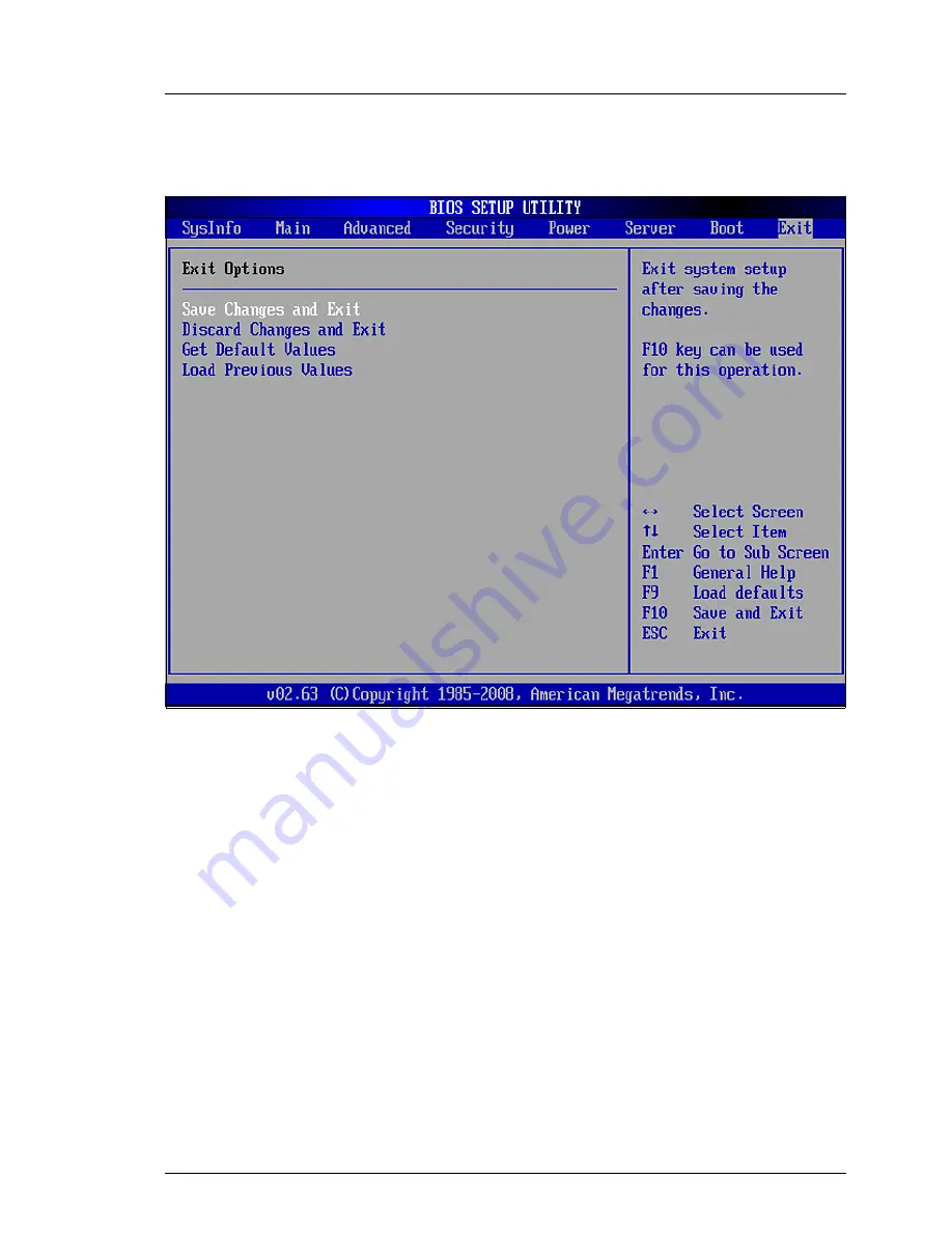
Exit menu 

Figure 17: "Exit" BIOS Setup menu

Save Changes and Exit

Saves all parameter changes of the current session and exits the BIOS 
Setup.

Discard Changes and Exit

Discards all parameter changes of the current session and exits the 
BIOS Setup.

Get Default Values

Resets all settings to the default values.

Load Previous Values

Undoes all changes made in the current session.

Summary of Contents for PRIMERGY BX620 S5

Page 1: ...PRIMERGY BX620 S5 Server Blade Operating Manual Edition July 2009 ...

Page 2: ...as created to meet the regulations of a quality management system which complies with the requirements of the standard DIN EN ISO 9001 2000 cognitas Gesellschaft für Technik Dokumentation mbH www cognitas de Copyright and Trademarks cognitas Gesellschft für Technik Dokumentation mbH 2009 Pfad W Anwendungsdaten FCT tim_local work PICHOL OBJ_DOKU 4478 003 fm Copyright 2009 Fujitsu Technology Solutio...

Page 3: ...E conformity 25 3 3 FCC Class A Compliance Statement 25 3 4 Transporting the Server Blade 26 3 5 Environmental protection 27 4 Installing the hardware 29 4 1 Installation procedure 29 4 2 Unpacking the Server Blade 30 4 3 Installing the Server Blade in the basic unit 31 4 4 Connecting the Server Blade 36 5 Installation and operation 39 5 1 Control and connection panel 40 5 2 Switching the Server B...

Page 4: ...ed Memory Options 62 6 5 4 Advanced Processor Options 63 6 6 Security menu 65 6 6 1 TPM Security Chip Setting 66 6 7 Power menu 67 6 8 Server menu 68 6 8 1 CPU STATUS 70 6 8 2 Memory Status 70 6 8 3 Console Redirection 70 6 8 4 IPMI 71 6 9 Boot menu 74 6 10 Exit menu 75 7 Troubleshooting and tips 77 8 CSS components 79 8 1 Replacing hot plug components 80 8 1 1 Hot plug hard disk drives 80 8 2 Rep...

Page 5: ...hree storage module variants allows you to create different configurations with SAS and SATA hard disks for different deployment scenarios The configuration options range from the low cost platform with SATA disks to the high end platform with SAS disks and a SAS storage module with RAID5 and Cache iTBBU Six onboard Ethernet channels with iSCSI support are available as communi cation interfaces an...

Page 6: ... a basic knowledge of the underlying operating system 1 2 Documentation overview I PRIMERGY manuals are available in PDF format on the PRIMERGY ServerView Suite DVD 2 The PRIMERGY ServerView Suite DVD 2 is part of the PRIMERGY ServerView Suite supplied with every server If you no longer have the ServerView Suite DVDs you can obtain the relevant current versions using the order number U15000 C289 T...

Page 7: ...ual Warranty manual Returning used devices manual Helpdesk leaflet Further sources of information PRIMERGY Abbreviations and Glossary on the PRIMERGY ServerView Suite DVD 2 Manual for the monitor Documentation for the boards and drives Operating system documentation Information files in your operating system ...

Page 8: ...ed in 2 banks and 3 channels These 12 slots for the main memory are suitable both for RDIMM registered DIMM and for UDIMM unbuffered DIMM memory modules You must use modules of the same size within a memory bank The maximum memory configuration when equipped with UDIMM memory modules is 24 GB capacities 1024 and 2048 MB and 96 GB when equipped with RDIMM memory modules capacities 2048 4096 and 819...

Page 9: ...n replacement of storage modules is described in the Options Guide LAN availability The BX620 S4 Server Blade has three onboard LAN controllers with TOE and iSCSI functionality which each provide two 1Gbit s Ethernet channels The connection to the Ethernet LAN is via switch blades or pass thru blades on the rear of the basic unit You will find more details in the operating manual for the basic uni...

Page 10: ... installed in the NET3 slot of the basic unit I It is not possible to mix different I O modules in one basic unit The installation of I O modules at a later time is described in the Options Guide Accessible Drives Accessible drives e g floppy disk or DVD drives can be connected via the two USB ports via breakout cable on the front of the server blade while the system is running Customer Self Servi...

Page 11: ... encryption using Windows Bitlocker Drive Encryption The TPM is activated via the system BIOS see chapter BIOS Setup V CAUTION When using the TPM note the program descriptions provided by the third party manufacturers You must also create a backup of the TPM content To do this follow the third party manufacturer s instructions Without this backup if the TPM or the system board is faulty you will n...

Page 12: ...logy from Fujitsu Technology Solutions PDA reports the threat of a system error or overloading early on so that preventive measures can be taken The ServerView Operations Manager enables the management of all PRIMERGY servers in the network via a central console The ServerView Operations Manager supports the following functions Round the clock monitoring regardless of server status High performanc...

Page 13: ...rating systems Service and support PRIMERGY servers are service friendly and modular thus enabling quick and simple maintenance The two redundant hot pluggable management blades of the BX600 S3 basic unit with independent LAN and COM ports for management enable comprehensive remote administration of the server blade Together they enable remote diagnosis for system analyses remote configu ration an...

Page 14: ...entions are used in this manual Text in italics indicates commands or menu items Quotation marks indicate names of chapters and terms that are being emphasized Ê describes activities that must be performed in the order shown V CAUTION pay particular attention to texts marked with this symbol Failure to observe this warning may endanger your life destroy the system or lead to the loss of data I ind...

Page 15: ...GB 4943 EN 50371 Electromagnetic compatibility FCC class A CNS 13438 class A VCCI class A AS NZS CISPR 22 class A GB 9254 class A GB 17625 interference emissions EN 55022 class A Harmonic current EN 61000 3 2 Flicker EN 61000 3 3 interference immunity EN 55024 EN 300386 CE marking to EU direc tives Low Voltage Directive 2006 95 EC product safety Electromagnetic compatibility 2004 108 EC Mechanical...

Page 16: ...s Weight Max 7 5 kg depending on the configuration Ambient conditions Condensation during operation must be avoided Japan VCCI China Taiwan BSMI Width 286 mm Depth 470 mm 520 mm incl handles and plugs Height 43 mm 1 slot in basic unit Environment class 3K2 Environment class 2K2 EN 60721 IEC 721 Part 3 3 EN 60721 IEC 721 Part 3 2 Temperature Operation 3K2 5 C 35 C Transport 2K2 20 C 60 C Humidity 1...

Page 17: ...spond to the details on the delivery note see the section section Unpacking the Server Blade on page 30 Ê Familiarize yourself with the controls and indicators on the front of the server blade see chapter Installation and operation on page 39 Ê Install the operating system and applications on the server blade When doing so you have the following options Clone server blade from a remote image serve...

Page 18: ... course install it directly without the ServerView Installation Manager I You will find more information on installing server blades remotely or locally in the ServerView Installation Manager manual This contains a Quick Start Guide as well as a detailed description of the individual installation options and wizards A print version of the ServerView Installation Manager manual is included in the S...

Page 19: ...the server in the intended environment please contact your sales outlet or our customer service team V CAUTION The actions described in this manual should only be performed by technical specialists Repairs to the device that do not relate to CSS failures must only be carried out by service personnel Please note that unauthorized inter ference with the system will void the warranty and exempt the m...

Page 20: ...from impacts and jolts Installation and operation V CAUTION Observe the notes on installation and operation in the operating manual for the basic unit If the device is integrated in an installation that receives power from an industrial public power supply network with the IEC309 connector the public power supply protection must comply with the requirements for non industrial public power supply n...

Page 21: ...rotection interference suppression Install only system extensions that satisfy the requirements and rules governing safety electromagnetic compatibility and telecommunica tions terminal equipment If you install other extensions you might damage the system or violate these safety regulations You can find out which system extensions are suitable from the customer service center or your sales outlet ...

Page 22: ...can break at high drive speeds data loss Under certain circumstances sharp CD DVD fragments can pierce the cover of the CD DVD drive equipment damage and can fly out of the device danger of injury particularly to uncovered body parts such as the face or neck I You can prevent mechanical damage and damage to the CD DVD drive as well as premature CD DVD wear by observing the following sugges tions O...

Page 23: ...n accordance with local regulations concerning special waste The battery must be disposed of in accordance with local regulations concerning special waste Replace the lithium battery on the system board in accordance with the instructions in the service supplement for the server blade All batteries containing pollutants are marked with a symbol a crossed out garbage can In addition the marking is ...

Page 24: ...tatic build up e g by touching a grounded object before working with such components Any devices or tools that are used must be free of electrostatic charge Wear a suitable grounding cable that connects you to the external chassis of the system unit Always hold components with ESDs at the edges or at the points marked green touch points Do not touch any connectors or conduction paths on an ESD Pla...

Page 25: ...ial installation This equipment generates uses and can radiate radio frequency energy and if not installed and used in strict accordance with the instructions may cause harmful interference to radio communications However there is no warranty that inter ference will not occur in a particular installation If this equipment does cause harmful interference to radio or television reception which can b...

Page 26: ...erences caused by such unauthorized modification substitution or attachment will be the responsibility of the user The use of shielded I O cables is required when connecting this equipment to any and all optional peripheral or host devices Failure to do so may violate FCC and ICES rules WARNING This is a class A product In a domestic environment this product may cause radio interference in which c...

Page 27: ...k Packaging information Do not throw away the packaging You may need it later for transporting the system If possible the equipment should only be transported in its original packaging Information on handling consumables Please dispose of printer consumables and batteries in accordance with the applicable national regulations In accordance with EU directives batteries must not be disposed of with ...

Page 28: ...ions branch or from our recycling center in Paderborn Fujitsu Technology Solutions GmbH Recycling Center D 33106 Paderborn Tel 49 5251 8 18010 Fax 49 5251 8 333 18010 The device must not be disposed of with domestic waste This device is labeled in compliance with European directive 2002 96 EC on waste electrical and electronic equipment WEEE This directive sets the framework for returning and recy...

Page 29: ...fore putting it into operation In the table the temperature difference is the difference between the operating environment temperature and the temperature to which the server blade was exposed previously outside transport or storage temperature 4 1 Installation procedure The following installation steps are described in detail in the subsequent sections of this chapter Unpacking the system see pag...

Page 30: ...Do not unpack the server blade until it is at its installation location Ê Unpack all the individual parts I Keep the original packaging in case you want to transport the server blade again Ê Check the delivery for any damage during transport Ê Check whether the items delivered match the details on the delivery note The product name and serial number of the product can be found on the identificatio...

Page 31: ...ill find detailed information on the configuration options in the operating manual for the basic unit V CAUTION Note the safety instructions and the information on handling electrostat ically sensitive devices in section Safety instructions on page 19 Removing the dummy module Any unused slots on the basic unit are fitted with appropriate dummy modules to comply with electromagnetic compatibility ...

Page 32: ...y module subsequently disengage Ê Push the upper handle up and the lower handle down at the same time 2 until the locking mechanism of the dummy module disengages and the dummy module is released Ê Pull the dummy module out of the slot completely 3 V CAUTION Keep the dummy module for future use If you remove a server blade and do not replace it with a new one you must reinstall the dummy module du...

Page 33: ...stallation in a BX600 S3 basic unit with management blade S3 If you install a BX620 S5 Server Blade in a BX600 S3 basic unit with management blade S3 that is switched on the server blade automat ically performs a Power On Self Test POST and then switches itself off again The server blade must not be switched off during the automatic boot process If the BX600 S3 basic unit is switched off when the ...

Page 34: ... Release the locking mechanism of the server blade handles by first pressing on the green touch points on the insides of the two handles 1 Ê Then rotate the release handles outward 2 into the unlocked position Ê Push the server blade as far as it will go into the slot holding the release handles in the unlocked position as you do this I Make sure the server blade is installed the correct way round...

Page 35: ... BX620 S5 Server Blade You remove the server blade in the same way as you remove the dummy module see Removing the dummy module on page 31 V CAUTION If you have removed a server blade and have not replaced it with a new one you must install a dummy module in the empty slot Ê Press the release handles inward until the locking mechanism engages completely ...

Page 36: ... unit When the server blade is installed in the blade server chassis midplane contacts automatically establish connec tions to the following modules on the rear of the basic unit Power supply units Management blade s for server administration KVM blade for connecting the keyboard mouse and monitor Ethernet switch blade s and or pass thru blade s for the LAN connection Fibre Channel switch blades o...

Page 37: ...t on the BX620 S5 Server Blade and special cable To connect external devices via the USB VGA port of the server blade you need a special cable with two USB connectors 2 and one VGA connector 3 I The USB VGA cable is delivered with the basic unit You will find information on connecting external devices via the infra structure modules of the basic unit in the operating manual for the basic unit 0 1 ...

Page 38: ... cognitas Gesellschft für Technik Dokumentation mbH 2009 Pfad W Anwendungsdaten FCT tim_local work PICHOL OBJ_DOKU 4483 003 fm ...

Page 39: ...in the basic unit The position and meaning of the elements on the control and connection panel of the server blade are explained in section 5 1 on page 40 Section 5 2 on page 43 provides information on the various ways in which the server blade can be switched on and off In section 5 3 on page 44 you find information on configuring the server blade with the ServerView Installation Manager Section ...

Page 40: ... cognitas Gesellschft für Technik Dokumentation mbH 2009 Pfad W Anwendungsdaten FCT tim_local work PICHOL OBJ_DOKU 4484 003 fm 5 1 Control and connection panel The following controls indicators and connectors are available Figure 7 BX620 S5 Server Blade control panel 2 3 4 5 6 7 1 8 9 ...

Page 41: ...is in standby mode ACPI function or is in a critical state Flashes green dark orange Server blade is in standby mode ACPI function and was selected for identification or this server blade is in a critical state 2 On Off button Fully compatible with the Advanced Configuration Power Interface ACPI If the basic unit is switched on 5 V standby voltage is present the server blade is switched off and yo...

Page 42: ...r is activated after the restart The indicator also lights up in standby mode 4 KVM button with integrated LED keyboard monitor mouse By pressing this button you switch the keyboard monitor and mouse to this server blade KVM MP error indicator bicolor LED Dark KVM was not activated for this server blade Lights up green KVM was activated for this server blade Flashes orange KVM was not activated fo...

Page 43: ... Lights up green LAN connection exists Flashes green LAN is active 7 USB VGA port Port for adapter cable with two USB ports for external devices e g floppy disk drive CD DVD drive or hard disk drive mouse or keyboard and one VGA port I A special cable is required See figure 6 on page 37 8 Hard disk access green LED Dark Hard disk drive is inactive Lights up green Hard disk drive is active 9 Hard d...

Page 44: ...the On Off button on the server blade item 2 in figure 7 on page 40 To switch the server blade off hold down the On Off button on the server blade item 2 in figure 7 on page 40 for 4 seconds Set switch on off time The server blade is switched on and off at the times defined in the ServerView Operation Manager After power failure Once a server blade has been switched on it will switch itself on aga...

Page 45: ...rView Installation Manager or to make changes at a later time the relevant server blade must be connected to a CD ROM DVD drive and a floppy disk drive via the USB VGA interface see the section Connecting the Server Blade on page 37 In addition a monitor keyboard and mouse must be connected to the KVM blade on the rear of the basic unit and are switched to the relevant server when the KVM key is p...

Page 46: ...he On Off switch item 2 in figure 7 on page 40 on the control panel of the server blade Ê Press the KVM button item 4 in figure 7 on page 40 on the control panel of the server blade to switch the keyboard mouse and monitor from the KVM blade to the server blade Wait a few seconds until the monitor is activated Ê Press F2 when prompted to call the BIOS Setup of the server blade Ê Select the Boot su...

Page 47: ... BX620 S5 Server Blade from the USB floppy disk drive as follows Ê Create a boot disk or a USB boot stick and copy the required BIOS and or BMC files to this disk Ê Connect the breakout cable to the relevant server blade Connect the USB floppy disk drive to the other end of the breakout cable Ê Switch the server blade on or restart it The firmware is updated automati cally I You may need to change...

Page 48: ... cognitas Gesellschft für Technik Dokumentation mbH 2009 Pfad W Anwendungsdaten FCT tim_local work PICHOL OBJ_DOKU 4484 003 fm ...

Page 49: ...the BIOS Setup The following overviews illustrate how the BIOS Setup menus are structured The numbers in brackets refer to the pages that contain the relevant descrip tions SysInfo System Overview System Information Page 1 55 System Information Page 2 56 Main System Overview System Time System Date 57 Sync RTC with Mgmt Blade 57 Boot Features 58 POST Errors 58 NumLock 58 Fast Boot 58 POST Diagnost...

Page 50: ... scrubbing 62 Memory Redundancy 62 Memory Power Mode 62 NUMA Optimization 62 Advanced Processor Options 60 CPU Mismatch Detection 63 Core Multi Processing 63 Enhanced SpeedStep 63 Enhanced Idle Power State 63 Virtualization Tech VT x 63 Virtualization Tech VT d 63 NX Memory Protection 63 Adjacent Cache Line Prefetch 64 Hardware Prefetch 64 Intel HT Technology 64 Intel Turbo Boost Tech 64 Limit CPU...

Page 51: ...Power Cycle Delay 69 Temperature Monitoring 69 Boot Retry Counter 69 CPU STATUS 69 CPU 1 Status CPU 2 Status 70 Memory Status 69 CPU 1 DIMM x y CPU 2 DIMM x y 70 Console Redirection 69 Port 70 Baud Rate 71 Protocol 71 Flow Control 71 Continue C R after POST 71 IPMI 69 SM Error Halt 71 Load iRMC Default Values 71 Event Log Full Mode 72 SDRR Version 72 LAN Settings 72 Management LAN 72 Management LA...

Page 52: ...6 1 Access Ê Start the server blade in cold boot or warm boot mode Ê Press the function key F2 Ê Enter the Setup password if assigned and confirm your entry by pressing the Return key Server Server Configuration continued Subnet Mask 73 Gateway Address 73 IPMI Status 72 IPMI Specification Version 73 iRMC Hardware 73 iRMC Firmware Version 73 Boot Boot Priority Order 1st Boot Device 2nd Boot Device ...

Page 53: ...keys À and  Workspace The information for the selected menu is displayed and settings are provided in the workspace on the left of the screen You select the required menu item using the arrow keys Ê and Ë A Ê at the left edge of the screen indicates a menu item that contains further submenus To display a submenu select the corresponding menu item and press the Return key Use the ESC key to return...

Page 54: ... value can be changed using the and keys If the parameter comprises several input areas e g time and date entries you can use the Tab key to move between the individual areas An asterisk in front of a menu item indicates configuration conflicts that must be resolved Information area The information area on the right of the screen displays brief infor mation on the selected menu item as well as inf...

Page 55: ...BX620 S5 Operating Manual 55 BIOS Setup SysInfo menu 6 3 SysInfo menu Figure 9 SysInfo BIOS Setup menu page 1 System Information Page 1 Displays information concerning the BIOS CPU and various IDs ...

Page 56: ...ft für Technik Dokumentation mbH 2009 Pfad W Anwendungsdaten FCT tim_local work PICHOL OBJ_DOKU 4485 003 fm Figure 10 SysInfo BIOS Setup menu page 2 System Information Page 2 Displays information on LAN MAC addresses including the LAN MAC address of the iRMC and COM ports ...

Page 57: ...you can position the cursor within the relevant input field and configure the values using or I If the system time and date are wrong after you switch off your server and restart it the lithium battery is flat and needs to be changed Sync RTC with Mgmt Blade Switches the synchronization of the Real Time Clock with the time of the management blade on Enabled or off Disabled I If this item is set to...

Page 58: ...e boot process NumLock Specifies whether NumLock for the numeric keypad is set On or not Off after you have switched the server on Fast Boot Specifies whether the boot process is speeded up Enabled or not Disabled by bypassing certain tests POST Diagnostic Screen Specifies whether the diagnosis screen is displayed Enabled or not Disabled during the boot phase Boot Menu Enables you to avoid the nor...

Page 59: ...ce the server blade is started the plug play functionality deter mines the new configuration data and initializes the installed boards and drives with this The field is set to No No Once the server blade is started the plug play functionality initializes the installed boards and drives with the configuration data currently valid Peripheral Configuration Calls a submenu for configuring the interfac...

Page 60: ...owing items Serial Use this input field to activate Enabled or deactivate Disabled the serial port Serial Port 1 Address Specifies the base I O address and the interrupt for the serial port 3F8h IRQ4 2F8h IRQ3 3E8h IRQ4 2E8h IRQ3 USB Host Controller This item allows the following USB settings USB Speed Specifies the speed at which the USB ports are operated USB 1 1 The USB 2 0 high speed host cont...

Page 61: ...SCSI is activated I The Port 1 Remote Boot item does not appear if LAN Controller n is set to Disabled The LAN Controller 1 Port 1 Remote Boot item is usually set to PXE The Port 2 Remote Boot item is only displayed if LAN Controller n is set to Port 1 2 Daughter Board OPROM Specifies whether the daughter board OPROM is active Enabled or not Disabled during the POST I This item does not appear if ...

Page 62: ...led This technology requires additional operating system and driver support 6 5 3 Advanced Memory Options You can make advanced memory configurations using the menu items in this submenu Memory scrubbing Specifies whether memory scrubbing is activated Enabled or deacti vated Disabled Memory Redundancy Specifies whether memory redundancy is activated or deactivated Disabled and if so what type Mirr...

Page 63: ...abled I This option is not provided by all ACPI capable operating systems Please read the operating system documentation for your server to configure this option correctly Enhanced Idle Power State Specifies whether low power mode is activated Enabled or deactivated Disabled during the idle phases of the CPU Virtualization Tech VT x Specifies whether additional hardware properties Vanderpool Techn...

Page 64: ...d I The use of this option depends on the various performance results for different applications Intel HT Technology Specifies whether Hyper Threading Technology is activated Enabled or deactivated Disabled Intel Turbo Boost Tech Specifies whether turbo mode is activated Enabled or deactivated Disabled Limit CPUID Function Specifies whether CPUID commands are to be processed with more than 3 funct...

Page 65: ...d has been assigned Installed or not Not Installed Set Supervisor Password Used for setting up or changing a user s password To delete a supervisor password open the window for assigning passwords and press Return twice Set User Password Used for setting up or changing a user s password Flash Write Specifies whether the BIOS flash memory is write protected Enabled or not Disabled ...

Page 66: ...the current TPM state Disabled Deactivated Enabled Activated No State Security Chip The TPM can be activated Enabled or deactivated Disabled Change TPM State Specifies the TPM state I This item is only displayed if Security Chip is set to Enabled and is also actually activated No Change No change Enabled Activated The TPM is released and activated Disabled Deactivated The TPM is locked and deactiv...

Page 67: ...ure 14 Power BIOS Setup menu Power Failure Recovery Specifies how the system behaves during recovery after a power failure Always Off Switches the system off Always On Switches the system on Previous State Switches to the state the system was in before the power failure ...

Page 68: ...5 Server BIOS Setup menu O S Boot Timeout Specifies whether a reset is performed Enabled or not Disabled after a specified timeout if the operating system could not be started Action Sets the action for a timeout of the operating system boot watchdog timer The following actions can be configured Continue Continue the boot process Reset Perform a reset Power Cycle Perform a cold boot Power Off Powe...

Page 69: ...and the following Power On in seconds 0 7 15 Temperature Monitoring Specifies whether the system can still be started when reaching a critical temperature Enabled or not Disabled Boot Retry Counter Specifies the number of boot attempts 0 3 7 after a failed boot process CPU STATUS Calls a submenu for specifying the CPU status see page 70 Memory Status Calls a submenu for specifying the memory statu...

Page 70: ...2 Memory Status CPU 1 DIMM x y CPU 2 DIMM x y Specifies the current status of the memory banks memory modules Enabled If the memory bank is populated the system memory module is used Disabled The memory module is not used by the system Failed If an error occurs in a memory module and it cannot be corrected or if the system makes a memory correction too often the status of the corresponding memory ...

Page 71: ...isabled Continue C R after POST Specifies whether communication with the terminal is also possible whilst the operating system is being loaded On or not Off I This item is only hidden if Port is set to Disabled 6 8 4 IPMI SM Error Halt Specifies the behavior during a system management error or during configuration changes Disabled A warning message is displayed Enabled Stops and shows Setup entrie...

Page 72: ...vent Logging continues despite the SEL being full The oldest entry is overwritten SDRR Version Shows the SDRR version number LAN Settings Calls a submenu for specifying the LAN parameters for the iRMC see page 72 IPMI Status Calls a submenu for displaying information on the IPMI controller see page 73 LAN Settings Management LAN Specifies whether communication between a remote system and the local...

Page 73: ...MC subnet mask 000 000 000 000 It is recommended to use the same settings as those used for the network card I This item is only hidden if Service LAN is set to Disabled It is grayed out if DHCP is set to Enabled It can be set if DHCP is set to Disabled Gateway Address Entry for configuring the iRMC gateway address 192 168 002 203 It is recommended to use the same settings as those used for the ne...

Page 74: ...chnik Dokumentation mbH 2009 Pfad W Anwendungsdaten FCT tim_local work PICHOL OBJ_DOKU 4485 003 fm 6 9 Boot menu Figure 16 Boot BIOS Setup menu 1st Boot Device 2nd Boot Device 3rd Boot Device Specifies the order in which the available devices are accessed during the boot process ...

Page 75: ... Exit Saves all parameter changes of the current session and exits the BIOS Setup Discard Changes and Exit Discards all parameter changes of the current session and exits the BIOS Setup Get Default Values Resets all settings to the default values Load Previous Values Undoes all changes made in the current session ...

Page 76: ... cognitas Gesellschft für Technik Dokumentation mbH 2009 Pfad W Anwendungsdaten FCT tim_local work PICHOL OBJ_DOKU 4485 003 fm ...

Page 77: ...to correct it as described in the chapter Troubleshooting and tips in the manual for the basic unit in the chapters for the installed components in the documentation for the connected devices in the help systems of the individual programs used If you do not manage to correct the problem proceed as follows Ê Make a note of the steps you have taken and the situation in which the fault occurred Also ...

Page 78: ... cognitas Gesellschft für Technik Dokumentation mbH 2009 Pfad W Anwendungsdaten FCT tim_local work PICHOL OBJ_DOKU 4486 003 fm ...

Page 79: ... PRIMERGY BX620 S5 server the following components are CSS components Hot plug components Hot plug hard disk drives The hot plug components can be extended or replaced during operation V CAUTION Only hard disk modules can be added or replaced while the system is running For all other system components the server blade must be switched off and in most cases must be removed from the basic unit excep...

Page 80: ...a module frame that allows you to replace defective drives and add new ones while the system is running The hard disk drive and the module frame are together referred to as the hard disk module V CAUTION A hard disk should only be removed from the hard disk module by a service technician All hard disk modules drives must be clearly labeled so that you can replace them in their original bays should...

Page 81: ... with hard disk drive installed 2 Indicators HDD Busy LED green HDD Fault LED orange Description see the table on page 40 in section Control and connection panel 3 Handle for locking and unlocking the HDD module 4 Button for locking and unlocking the handle 5 Ridge for the application of a sticker with the current drive name 6 Dummy module 7 Tabs for unlocking the dummy module 1 2 3 4 5 6 7 ...

Page 82: ...rules to prevent such problems occurring Only store and transport HDD modules within the limits stipulated in the specification When transporting HDD modules even over short distances always use the original packaging ESD label Never expose HDD modules to a temperature shock Avoid the formation of condensation inside and on the outside of the hard disk drive V CAUTION The HDD module must be acclim...

Page 83: ...gether the two tabs 1 on the dummy module until the locking mechanism is released and pull the dummy module out of the bay A V CAUTION Keep the dummy module for future use If the hard disk module is removed again and not replaced with a new one the dummy module must be reinstalled to comply with EMC regulations cooling require ments and fire protection measures I To reinstall the dummy module late...

Page 84: ...ocal work PICHOL OBJ_DOKU 4678 001 fm Installing a hard disk module Figure 20 Hot pluggable hard disk module Ê Press the green catch lever 1 to the left and swivel the locking lever 2 to the front Ê Keeping the locking lever open push the hard disk module as far as possible into the bay of the server blade Figure 21 Inserting and engaging the hard disk module 2 1 ...

Page 85: ...back in their original bays later If you mix up the hard disks you might lose existing data Proceed as follows to replace a hard disk module during operation Ê Press on the green ejection lever in the direction of the punched in triangle and pull out the defective hard disk module holding it by the opened handle Ê Wait at least 60 seconds so that the RAID controller can recognize that a hard disk ...

Page 86: ... Ê Press the On Off button on the server blade control panel Ê Pull the server blade out of the basic unit see Removing the server blade from the basic unit on page 87 Ê Open the server blade see Removing the cover on page 89 Ê Press the Indicate CSS button on the system board see Identifying CSS components on page 90 The PRIMERGY diagnostic LED see service supplement of the defective CSS componen...

Page 87: ... hot plug components Removing the server blade from the basic unit Figure 22 Removing the server blade Ê Press the two green touch points 1 to unlock the ejection levers Ê Open out the two ejection levers 2 simul taneously to disengage the server blade 1 1 2 2 ...

Page 88: ...ts CSS components cognitas Gesellschft für Technik Dokumentation mbH 2009 Pfad W Anwendungsdaten FCT tim_local work PICHOL OBJ_DOKU 4678 001 fm Figure 23 Removing the server blade Ê Pull the server blade out of the basic unit and place it on an antistatic surface ...

Page 89: ...oving the cover Figure 24 Removing the cover Ê Press the two touch points 1 of the cover simultaneously to disengage it and slide back the cover as far as it will go in the direction of the arrow 2 Ê Take off the cover plate The server blade components are now freely accessible 1 1 2 ...

Page 90: ...aten FCT tim_local work PICHOL OBJ_DOKU 4678 001 fm Identifying CSS components Figure 25 Position of Indicate CSS button on the system board Ê Press the Indicate CSS button on the system board The PRIMERGY diagnostic LED see service supplement of the defective CSS component glows orange and shows which CSS component on the system board must be replaced ...

Page 91: ... memory module Ê Flip out the fastening tabs on both sides of the relevant slot 1 Ê Remove the memory module from the slot 2 Installing a new memory module V CAUTION Observe the fitting rules in the options guide Figure 27 Installing a memory module Ê Carefully press the memory module into the slot 1 until the fastening tabs on both sides of it engage 2 1 1 2 2 2 1 ...

Page 92: ... of the server blade on the housing at a distance of 1 2 cm from the frame such that the cover lies flush with the edges on both sides Ê Push the cover forward in the direction of the arrow see figure 28 until it engages Ê Insert the server blade in the basic unit I To insert the server blade follow the procedure described in Removing the server blade from the basic unit on page 87 in reverse Ê Pr...

Page 93: ...5 data security 11 defining switch on time 44 delivery note 30 disposal of devices 28 dummy module installing 31 server blade 31 E ECC 11 electrical specifications 15 electromagnetic compatibility 15 25 electrostatic sensitive devices ESD 24 EMC directive 15 environment class 16 environmental protection 27 error correcting code 11 ESD electrostatic sensitive devices 24 F FCC statement 25 fibre cha...

Page 94: ...regulations and standards 15 S Safety instructions 19 safety standards 15 SAS 8 SATA 8 saving energy 27 security functions 5 serial number 30 server ambient conditions 16 dimensions 16 electrical specifications 15 product name 30 safety standards 15 serial number 30 technical data 15 transport 26 ventilation space 16 weight 16 server blade close 92 connection panel 40 control panel 40 CPU 8 dummy ...

Page 95: ...hnical data 15 TPM 11 transport server 26 transport damage 30 Troubleshooting and tips 77 Trusted Platform Module 11 U UDIMM 8 unbuffered DIMM 8 unpacking server blade 30 update BIOS 46 BMC 46 firmware 46 USB VGA port 43 V ventilation space 16 W weight 16 ...

Page 96: ... cognitas Gesellschft für Technik Dokumentation mbH 2009 Pfad W Anwendungsdaten FCT tim_local work PICHOL OBJ_DOKU 4488 003 fm ...

Reviews: