2-22
Assembling and Installing Connectivity Peripherals
4.
Connect the AC adapter’s AC power cable to the AC supply wire in the junction box. To do so, cut
the wall plug off of the AC adapter’s AC power cable and discard the wall plug. Trim the end of the
cable that connects to the AC adapter to a length of about 2’ and connect the cable wires directly to
the AC supply wires in the junction box. Use twist-on wire connectors or other approved connectors
in compliance with electrical codes.
5.
Coil the DC supply cable of the AC adapter so that it consists of “figure-eight” loops about 3” long
and tie the coiled cable using the tie wrap supplied with the AC adapter. Leave about 8” of wire on
the DC connector end free.
Figure 2-13. Coiling DC Supply Cable
6.
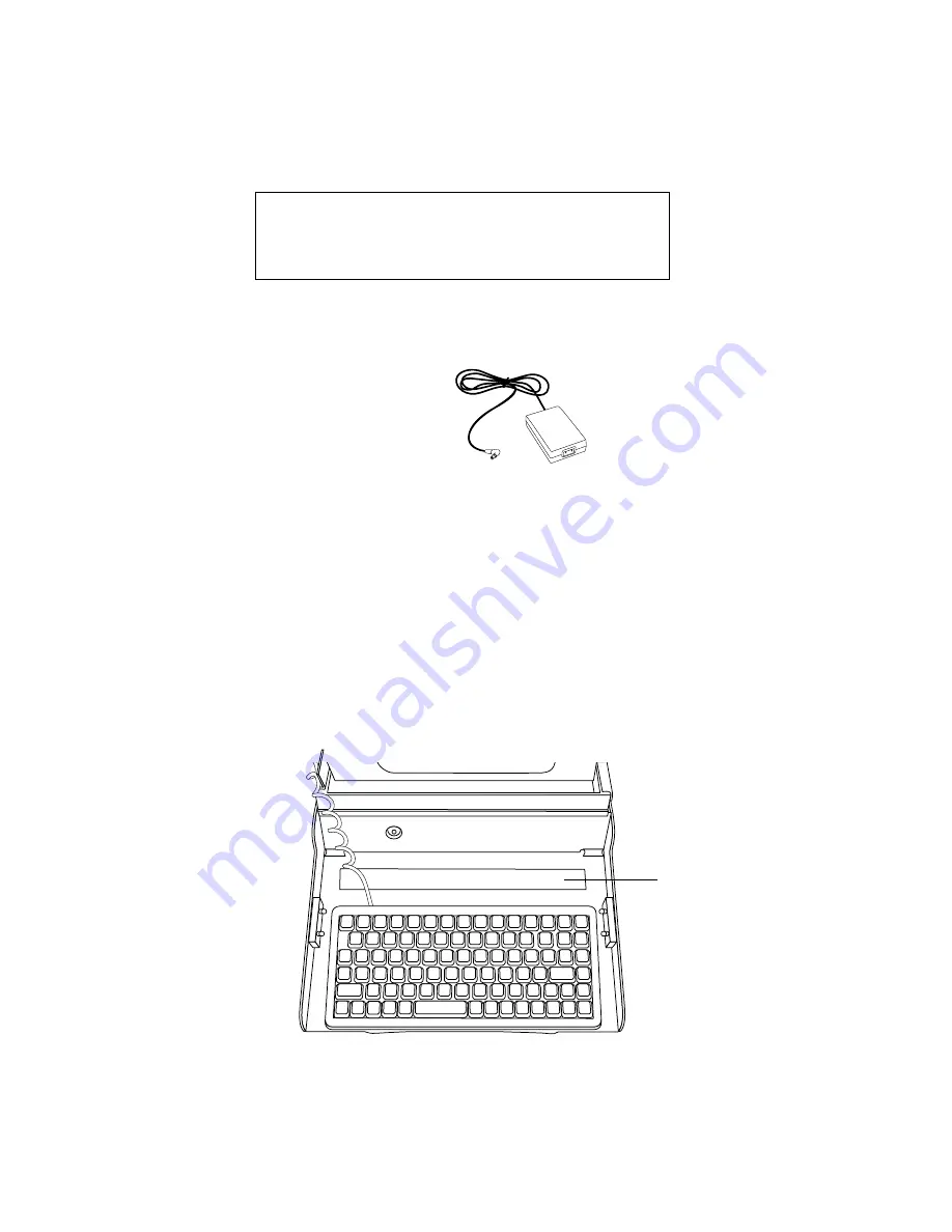
Attach the keyboard to the keyboard tray. Note that two different keyboards are supported for use
with the wall-mount cradle. Choose one of the following methods to attach the keyboard depending
on which type of keyboard you are installing:
• FMWKB1 keyboard: Remove the protective backing from the Velcro strips on the keyboard tray
and place the keyboard on the tray in the desired position as shown in Figure 2-15 on page 2-23.
• FMWKB3 keyboard: Remove the protective backing from the Velcro strip closest to the edge of
the keyboard tray (closest to the user) and place the keyboard on the tray as shown in Figure 2-14.
Ensure that the keyboard is centered in the keyboard tray and ensure that the keyboard is all the
way forward (toward the user) in the keyboard tray. Note that since this keyboard is smaller, the
rear Velcro strip is not used and can be removed if desired.
Figure 2-14. Installing an FMWKB3 Keyboard
Note:
The FMWKB2 keyboard is not supported for use with the wall-mount cradle.
Warning
Shut off power before working on a circuit. Use approved
materials and conform to all electrical codes.
~3”
~8”
DC Supply Cable
This Velcro strip is not used.
Summary of Contents for Point 1600
Page 1: ...Connectivity Peripherals Installation Guide Point 510 Point 1600 ...
Page 2: ......
Page 3: ...Connectivity Peripherals Installation Guide Point 510 Point 1600 ...
Page 6: ......
Page 8: ...vi ...
Page 10: ...viii About This Guide ...
Page 48: ...2 32 Assembling and Installing Connectivity Peripherals ...
Page 50: ...I 2 ...
Page 51: ......
Page 52: ...1 99 58 0627 00A ...


