4.2 Subassemblies
C141-E145-02EN
4-3
MHR2040AT
3
1
2
0
Head
Head
MHR2020AT
1
0
MHR2030AT
1
2
0
3
Head
(Either of head 0 or
head 3 is mounted.)
Head
MHR2010AT
1
0
(Either of head 0 or
head 1 is mounted.)
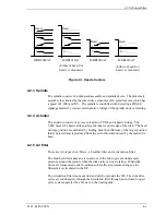
Figure 4.1 Head structure
4.2.3 Spindle
The spindle consists of a disk stack assembly and spindle motor. The disk stack
assembly is activated by the direct drive sensor-less DC spindle motor, which has
a speed of 4,200 rpm
±
1%. The spindle is controlled with detecting a PHASE
signal generated by counter electromotive voltage of the spindle motor at starting.
4.2.4 Actuator
The actuator consists of a voice coil motor (VCM) and a head carriage. The
VCM moves the head carriage along the inner or outer edge of the disk. The head
carriage position is controlled by feeding back the difference of the target position
that is detected and reproduced from the servo information read by the read/write
head.
4.2.5 Air filter
There are two types of air filters: a breather filter and a circulation filter.
The breather filter makes an air in and out of the DE to prevent unnecessary
pressure around the spindle when the disk starts or stops rotating. When disk
drives are transported under conditions where the air pressure changes a lot,
filtered air is circulated in the DE.
The circulation filter cleans out dust and dirt from inside the DE. The disk drive
cycles air continuously through the circulation filter through an enclosed loop air
cycle system operated by a blower on the rotating disk.
Summary of Contents for MHR2010AT
Page 1: ...C141 E145 02EN MHR2040AT MHR2030AT MHR2020AT MHR2010AT DISK DRIVES PRODUCT MANUAL ...
Page 4: ...This page is intentionally left blank ...
Page 8: ...This page is intentionally left blank ...
Page 10: ...This page is intentionally left blank ...
Page 12: ...This page is intentionally left blank ...
Page 32: ...This page is intentionally left blank ...
Page 38: ...This page is intentionally left blank ...
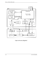
Page 58: ...Theory of Device Operation 4 6 C141 E145 02EN Figure 4 3 Circuit Configuration ...
Page 188: ...Interface 5 114 C141 E145 02EN g d f f d e Figure 5 7 Normal DMA data transfer ...
Page 240: ...This page is intentionally left blank ...
Page 242: ...This page is intentionally left blank ...
Page 246: ...This page is intentionally left blank ...
Page 248: ...This page is intentionally left blank ...
Page 249: ......
Page 250: ......

