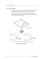
4.5 Cable Connections
C156-E228-02EN 4-13
4.4.2 Mounting procedure
How the drive is mounted depends on the system cabinet structure. Determine the
mounting procedure in consideration of the requirements of each system. This
section contains the general mounting procedure and check items.
See Section 3.2 for details on mounting drive.
1) For a system with an external operator panel mounted, connect the external
operator panel cable before mounting the drive in the system cabinet because
it is difficult to access the connector after the drive is mounted.
2) Tighten four mounting screws to secure the drive in the system cabinet.
The drive has ten mounting holes (both sides: 3
×
2, bottom: 4). Secure the
drive using the four mounting holes on both sides or the bottom.
Use mounting screws whose lengths are 3 mm or less from the external wall
of the mounting frame of the drive when they are tightened. (See Figure
3.6)
When mounting with screws, the screw tightening torque should be 0.4 to
0.45Nm (4 to 4.6kgf-cm).
Be careful not to damage the parts on the PCA when mounting the drive.
3) After securing the drive, make sure that the drive does not touch the chassis of
the system cabinet. There must be at least 1.5 mm clearance between the
drive and chassis. (See Figure 3.6)
4.5 Cable Connections
Use the following cables to connect the drive to the system. See Subsection 3.4.2
for details on the connector positions and cable requirements.
•
Power supply cable
•
SCSI cable
•
External operator panel cable (if required)
The general procedure for cable connection and notes on connecting cables are
given below. Pay attention to the insertion direction of each cable connector.
1) Make sure that the system power is off.
2) Do not connect or disconnect any cable when the power is on.
1) Connect the power cable.
2) Connect the external operator panel (only if required for the system).
3) Connect the SCSI cable.
Summary of Contents for MCM3064SS
Page 1: ...C156 E228 02EN MCM3064SS MCM3130SS MCP3064SS MCP3130SS OPTICAL DISK DRIVES PRODUCT MANUAL ...
Page 4: ...This page is intentionally left blank ...
Page 8: ...This page is intentionally left blank ...
Page 20: ...This page is intentionally left blank ...
Page 30: ...This page is intentionally left blank ...
Page 42: ...Specifications 2 12 C156 E228 02EN Figure 2 3 Example of alternate processing ...
Page 47: ...3 2 Mounting Requirements C156 E228 02EN 3 5 Figure 3 2 Outer dimensions 1 of 2 ...
Page 49: ...3 2 Mounting Requirements C156 E228 02EN 3 7 Figure 3 3 Outer dimensions 1 of 3 ...
Page 51: ...3 2 Mounting Requirements C156 E228 02EN 3 9 Figure 3 3 Outer dimensions 3 of 3 ...
Page 82: ...Installation 4 16 C156 E228 02EN Figure 4 6 SCSI connection check ...
Page 84: ...This page is intentionally left blank ...
Page 98: ...This page is intentionally left blank ...
Page 148: ...SCSI BUS 7 46 C156 E228 02EN Figure 7 21 Bus phase sequence 1 of 2 ...
Page 149: ...7 8 Bus Sequence C156 E228 02EN 7 47 Figure 7 21 Bus phase sequence 2 of 2 ...
Page 158: ...This page is intentionally left blank ...
Page 166: ...This page is intentionally left blank ...
Page 168: ...This page is intentionally left blank ...
Page 169: ......
Page 170: ......


