background image

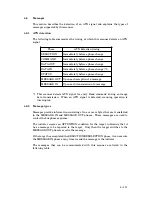
The target terminates the DATA IN phase when mode sense data for the
number of bytes specified in this field is transferred or when the tarnsfer of all
valid mode sense data is completed.

(2)

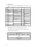
Mode data:  DATA IN phase (Target to Initiator)

Mode parameter list data consists of a header, 0 or more than one descriptor block,
and 0 or more than one page.

a. Header

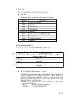
Mode parameter data (header) is as follows:

Byte 0

1

2

3

Mode data length

Reserved

a a a a a a a a a a a a

a a a a a a a a a a a a

a a a a a a a a a a a a

a a a a a a a a a a a a

7

a a a a a a a a a a a

a a a a a a a a a a a

a a a a a a a a a a a

a a a a a a a a a a a

6

a a a a a a a a a a a

a a a a a a a a a a a

a a a a a a a a a a a

a a a a a a a a a a a

5

a a a a a a a a a a a a

a a a a a a a a a a a a

a a a a a a a a a a a a

a a a a a a a a a a a a

4

a a a a a a a a a a a

a a a a a a a a a a a

a a a a a a a a a a a

a a a a a a a a a a a

3

a a a a a a a a a a a a

a a a a a a a a a a a a

a a a a a a a a a a a a

a a a a a a a a a a a a

2

a a a a a a a a a a a

a a a a a a a a a a a

a a a a a a a a a a a

a a a a a a a a a a a

1

a a a a a a a a a a a a

a a a a a a a a a a a a

a a a a a a a a a a a a

a a a a a a a a a a a a

0

Block descriptor length

f

Mode data length:  Byte 0

The length of available data to be successively transferred is specified in the
mode data length in bytes.  The mode data length itself is not included.

f

Block descriptor length:  Byte 3

The block descriptor length specifies the length of the entire mode parameter
descriptor block in bytes.  The page and vendor

>

specific parameter are not

included.

0 is specified.

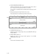
b. Mode parameter descriptor block (omitted in this scanner)

The mode parameter data (mode descriptor block) is as follows:

Byte 0

1

2

3

4

5

6

7

Reserved

(MSB)

Number of blocks

(LSB)

a a a a a a a a a a a a

a a a a a a a a a a a a

a a a a a a a a a a a a

a a a a a a a a a a a a

7

a a a a a a a a a a a

a a a a a a a a a a a

a a a a a a a a a a a

a a a a a a a a a a a

6

a a a a a a a a a a a

a a a a a a a a a a a

a a a a a a a a a a a

a a a a a a a a a a a

5

a a a a a a a a a a a a

a a a a a a a a a a a a

a a a a a a a a a a a a

a a a a a a a a a a a a

4

a a a a a a a a a a a

a a a a a a a a a a a

a a a a a a a a a a a

a a a a a a a a a a a

3

a a a a a a a a a a a a

a a a a a a a a a a a a

a a a a a a a a a a a a

a a a a a a a a a a a a

2

a a a a a a a a a a a

a a a a a a a a a a a

a a a a a a a a a a a

a a a a a a a a a a a

1

a a a a a a a a a a a a

a a a a a a a a a a a a

a a a a a a a a a a a a

a a a a a a a a a a a a

0

Reserved

(MSB)

Block length

(LSB)

$

 106

Summary of Contents for M3093DG

Page 1: ...M3096GX M3093GX M3093DG IMAGE SCANNER OEMMANUAL C150 E015 03EN ...

Page 2: ......

Page 3: ...f this manual is subject to change without prior notice All Rights Reserved Copyright 1994 1996 1997 FUJITSU LIMITED Edition 01 Nov 1994 First Edition Jul 1996 02 Production ID setting procedure and white level following procedure added error corrected M3093DG added Jan 1997 03 Error corrected i ...

Page 4: ...This page is intentionally left blank i i ...

Page 5: ...ession circuit 2 CMP 2 M3096GX M3093GX 2 7 2 3 3 Memory M3093DG 2 7 CHAPTER 3 CONFIGURATION 3 1 3 1 Dimensions 3 1 3 2 Circuit Configuration 3 3 3 3 Carrier Fixing Bracket Removal 3 4 3 4 Power Switch 3 6 3 5 Indication Panel Functions 3 8 3 5 1 Indicators 3 8 CHAPTER 4 INTERFACE 4 1 4 1 Physical Specifications 4 3 4 2 SCSI Bus 4 6 4 2 1 System configuration 4 6 4 2 2 Bus signals 4 7 4 2 3 Bus sig...

Page 6: ...111 4 6 1 ATN detection 4 111 4 6 2 Message types 4 111 4 7 Command Sequence 4 121 4 7 1 Initial sequence 4 121 4 7 2 Command sequence to read 4 122 4 7 3 READ command sequence 4 125 4 7 3 1 Multiple read M3096GX M3093GX without CMP 2 option disconnect disabled 4 125 4 7 3 2 Multiple read M3096GX M3093GX without CMP 2 option disconnect enabled 4 126 4 7 3 3 Single read M3096GX M3093GX with CMP 2 o...

Page 7: ...A 8 A 5 Job Separation Sheet A 9 A 5 1 Shape A 9 A 5 2 Paper conditions A 9 APPENDIX B ADF SCANNING SPEED B 1 APPENDIX C DROP OUT COLOR C 1 C 1 Print Density Measurement C 1 C 2 Drop out Color Standard C 2 APPENDIX D DIFFERENCES BETWEEN THE M3096GX AND M3096G IMAGE SCANNERS D 1 D 0 Preface D 1 D 1 Enhanced Functions and Functional Differences D 2 D 1 1 Functions added D 3 D 1 1 1 Paper size detect...

Page 8: ...13 D 2 3 3 Threshold D 13 D 2 3 4 Downloaded dither pattern and Brightness D 13 D 2 3 5 Simplified DTC D 14 APPENDIX E CHANGING PRODUCT IDENTIFICATION E 1 E 1 Change from M3093GX or M3096GX to M3096G E 2 E 2 Change from M3093GX or M3096GX to M3097G E 4 E 3 Change from M3093DG to M3093GX M3096G M3099G E 5 APPENDIX F WHITE LEVEL FOLLOWING ALGORITHM F 1 vi ...

Page 9: ... 6 3 4 M3096GX M3093GX DG Indication panel 3 8 4 1 Pin assignment 4 5 4 2 Phase sequence 4 10 A 1 Paper size specification A 2 A 2 1 Areas that must not be perforated M3096GX A 6 A 2 2 Areas that must not be perforated M3093GX DG A 7 A 3 Grounding color area A 8 C 1 Spectrum band C 2 D 1 1 Command sequence D 3 E 1 Sensor location E 2 vii ...

Page 10: ...This page is intentionally left blank viii ...

Page 11: ...pecifications 4 4 4 2 Bus phases vs signal drive sources 4 8 4 3 Method of driving the interface signal 4 9 4 4 Signal delay times definition 4 10 4 5 INFORMATION TRANSFER phase type 4 17 4 6 Commands 4 23 D 1 1 Added functions D 2 D 1 2 Functional differences D 2 E 1 Product ID display mode E 5 E 2 Product ID change mode E 5 ix ...

Page 12: ...This page is intentionally left blank x ...

Page 13: ...ctronic filing systems facsimiles optical character readers OCR computer aided design CAD systems and automatic publishing systems The M3096GX can scan double letter or A3 size paper and M3093GX DG can scan letter or A4 size paper These scanners have an automatic document feeder ADF that can accommodate up to 50 pages M3093DG supports letter or A4 size duplex scanning 1 1 ...

Page 14: ...Figure 1 1 M3096GX Figure 1 2 M3093GX DG 1 2 ...

Page 15: ...r Up to 50 pages A4 64 g m2 paper weight can be loaded into the document feeder 3 High quality image These scanners use a compact optical system that provides sharper focus Furthermore the use of new LSI chips produce finer image 4 New image processing The standard version of this scanner has error diffusion function Dithering or error diffusion can be applied to those areas judged to be photograp...

Page 16: ...This page is intentionally left blank 1 4 ...

Page 17: ...ity MAX 50 55 kg continuous forms A4 paper 6 Resolution Horizontal scanning 400 dpi Vertical scanning 800 600 400 300 240 200 dpi 7 Gray scale 256 steps 8 Interface SCSI 9 Scanning speed MAX 297 432 mm MIN 210 148 mm MAX 216 355 mm MIN 210 148 mm Flatbed ADF A4 200 dpi 2 0 s A3 400 dpi 5 6 s A4 200 dpi 21 ppm letter 200 dpi 22 ppm MAX 297 432 mm A4 200 dpi 1 6 s M3093DG M3096GX M3093GX MAX 216 355...

Page 18: ...anning 50 dpi to 800 dpi Horizontal scanning and vertical scanning are independent Standard Standard If CMP 2 option is installed Fixed binarization Dither Error diffusion method If the image processing option is installed Separation image emphasis extraction mirror image inversion outline simplified DTC Dynamic threshold smoothing filtering noise removing Non MH MR or MMR Standard If option is in...

Page 19: ...tions Zooming is a function of the IPC 2D option It may be used as a magnifying glass for viewing signatures details on a map fingerprints or other features of a document Normally a specific area of the document is specified for use with the zooming capability IPC 2D can zoom in on images in increments specified as percentages or dpi depending on the user interface of the imaging application used ...

Page 20: ...urge current A 50 or less 6 Momentary power failure 100 0 5 Hz 7 Leakage current mA 0 75 or less 8 Dielectric strength AC 1 5 KV or more for one minute or more between FG and AG lines AC line noise 9 Voltage 1 2 KV pulse duration 5 os 10 11 Operating 20 to 80 no condensation Nonoperating 8 to 95 no condensation Operating 0 2 Nonoperating 0 4 12 Indication Operating 5 Nonoperating 10 13 ESD KV 8 or...

Page 21: ...ecifying required values for threshold curve setting smoothing mode and filtering mode Noise removal reduces noise often found in images after dynamic threshold processing Threshold curve setting smoothing mode filtering mode and noise removal are all dynamic threshold circuit DTC functions 1 Threshold curve setting The contrast level of the dynamic threshold circuit can be changed with setting 3 ...

Page 22: ...lying dither processing or error diffusion for the photo and the binarizing for the line drawing 2 Outline extraction Extracts the outline of the Line drawing such as a thick character 3 Image emphasis Emphasizes the black white contrast to raise the resolution 4 Inversion White black conversion Converts white into black and black into white of read data binary data 5 Mirror image Turns over the b...

Page 23: ...MH MR MMR 2 3 3 Memory M3093DG The following SIMM memory option is provided for M3093DG f Memory M3093DE B182 When the output resolution is more than 401 dpi the memory option is required If the memory option is not installed the video data is limited to 3456 5600 pixels 2 7 ...

Page 24: ...This page is intentionally left blank 2 8 ...

Page 25: ...imensions 3 2 Circuit Configuration 3 3 Carrier Fixing Bracket Removal 3 4 Power Switch 3 5 Indication Panel Functions 3 1 Dimensions Figure 3 1 1 shows the dimensions of M3096GX Figure 3 1 2 shows the dimensions of M3093GX DG 3 1 ...

Page 26: ...a a a a a a a a a a a a a a a a a a a a a a a a a a 696 Unit mm 497 173 Figure 3 1 2 Dimensions of M3093GX DG Unit mm 376 173 M3093GX 198 M3093DG a a a a a a a a a a a a a a a a a a a a a a a a a a a a a a a a a a a a a a a a a a a a a a a a a a a a a a a a a a a a a a a a a a a a a a 530 3 2 ...

Page 27: ...ding stepping motor and motor driver circuit f Control circuit MPU circuit f Power section Figure 3 2 is the function block diagram of this scanner Figure 3 2 Function block diagram Motor driver circuit Power section Control circuit MPU circuit Power switch Image processing circuit option Indication panel Mechanism section Flatbed ADF Controller 100 to 120 VAC 220 to 240 VAC Video circuit 1 SIMM M...

Page 28: ...side a a a a a a a a a a a a a a a a a a a a a a a a a a a a a a a a a a a a a a a a a a a a a a a a a a a a a a a a a a a a a a a a a a a a a a a a a a a a a a a a a a a a a a a a Correct a a a a a a a a a a a a a a a a a a a a a a a a a a a a a a a a a a a a a a a a a a a a a a a a a a a a a a a a a a a a a a a a a a a a a a a a a a a a a a a a a a a a a a a a a a a a a a a a a a a a a a a a a a...

Page 29: ...he carrier fixing bracket from position Then install the carrier fixing bracket at position ADF Upper Viewed from below Carrier bracket position during operation Carrier bracket position during transportation Note When the scanner is transported be sure that the carrier fixing bracket is inposition ...

Page 30: ...3 4 Power Switch Figure 3 3 shows the location of the power switch Figure 3 3 1 Power switch M3096GX Power switch Figure 3 3 2 Power switch M3093GX 3 6 ...

Page 31: ...Figure 3 3 3 Power switch M3093DG 3 7 ...

Page 32: ...a a a a a a a a Read a a a a a a a a a a a a a a a a a a a a a a a a a a a a a a a a a a a a a a a a a a a a Check a a a a a a a a a a a a a a a a a a a a a a a a a a a a a a a a a a a a a a a a a a a a a a a a a a a a a a a a a a a a a a a a a Indicators 3 5 1 Indicators The meaning of each indicator is as follows Power indicator Green Lights to indicate the power is on Read reading in progress i...

Page 33: ...ner as well as descriptions peculiar to the scanner For details of SCSI refer to the ANSI standard The following terms are needed to understand this section f SCSI device A host adapter or a target controller that can be attached to the SCSI bus f Initiator An SCSI device usually a host system that requests an I O process to be performed by another SCSI device a target f Target An SCSI device that...

Page 34: ... f OBJECT POSITION f MODE SELECT 6 f MODE SENSE 6 f READ f RELEASE UNIT f REQUEST SENSE f RESERVE UNIT f SEND f SEND DIAGNOSTIC f SET SUBWINDOW f SET WINDOW f TEST UNIT READY f SCAN A control byte is not supported If the value other than X 00π is specified an error is generated 4 Statuses The following statuses are supported by this scanner f BUSY f CHECK CONDITION f GOOD f RESERVATION CONFLICT 4 ...

Page 35: ...SAVE DATA POINTER f SYNCHRONOUS DATA TRANSFER REQUEST 6 Others The bits and fields for which the word Reserved is described are checked For a non zero an error is returned 4 1 Physical Specifications The devices linked to this interface are daisy chained with each other A terminator is attached to the ends of the interface Interface specifications are shown below 1 Connection Terminator SCSI devic...

Page 36: ...cteristics Connector pin assignments for signal lines 6 m 132 25 signal twisted pair e 0 1 mm from main cable in scanner to internal wiring See the figure under 3 Open collector or three state driver Low level true 0 0 to 0 5 VDC High level false 2 5 to 5 25 VDC Output current 48 mA corresponding output voltage e 0 5 V Low level true 0 0 to 0 8 VDC High level false 2 0 to 5 25 VDC Input load 0 4 m...

Page 37: ... 33 DB 7 GND 9 34 DB P GND 10 35 GND GND 11 36 GND Reserved 12 37 Reserved Open 13 38 TERMPWR Reserved 14 39 Reserved GND 15 40 GND GND 16 41 ATN GND 17 42 GND GND 18 43 BSY GND 19 44 ACK GND 20 45 RST GND 21 46 MSG GND 22 47 SEL GND 23 48 C D GND 24 49 REQ GND 25 50 I O Signal name Pin number Signal name Note Reserved pins are connected to GND 4 5 ...

Page 38: ...CSI ID provides identification for specifying particular SCSI device when an initiator selects a target or when a target reconnects an initiator SCSI ID also represents the priority for using the bus in the arbitration phase A description regarding the bus phase is given later Priorities are given in the descending order of data bus bit numbers DBn with the highest priority placed on ID 7 DB7 and ...

Page 39: ...RATION phase Control signals BSY Busy An ORtied signal that indicates that the bus is being used SEL Select An ORtied signal used either by an initiator to select a target or by a target to reselect an initiator RST Reset An ORtied signal that indicates the RESET condition C D Control Data I O Input Output MSG Message The C D I O and MSG signals are used to distinguish between the different inform...

Page 40: ...her more different drive methods may coexist for a signal on the bus Table 4 2 Bus phases vs signal drive sources 1 2 Signal Bus phase BSY SEL I O C D MSG REQ ACK DB7 to 0 DBP ATN RST BUS FREE N N N N N N N N A ARBITRATION A W N N N N ID N A SELECTION I T I N N N I I I A RESELECTION I T T T T T I T I A COMMAND T N T T T I I I A DATA IN T N T T T I T I A DATA OUT T N T T T I I I A STATUS T N T T T ...

Page 41: ...ator target or both as specified in the SELECTION phase and RESELECTION phase Table 4 3 Method of driving the interface signal OR connection No signal is driven by any SCSI device Signal status is made false by the termination resistor circuits NON OR connection The signal is driven false by a certain SCSI device initiator or target or is not driven by any SCSI device False True A SCSI device driv...

Page 42: ...rt REQ or REQB while using synchronous data transfers Also the minimum time that an initiator shall assert ACK while using synchronous data transfers 3 Bus Clear delay 800 ns The maximum time for an SCSI device to stop driving all bus signals after 1 The BUS FREE phase is detected BSY and SEL both false for a bus settle delay 2 SEL is received from another SCSI device during the ARBITRATION phase ...

Page 43: ...the transition of the I O signal from false to true 9 Deskew delay 45 ns The minimum time required for deskew of certain signals 10 Disconnection delay 200 os The minimum time that a target shall wait after releasing BSY before participating in an ARBITRATION phase when honoring a DISCONNECT message from the initiator 11 Hold time 45 ns The minimum time added between the assertion of REQ or REQB o...

Page 44: ...ded The minimum time required for an initiator or target in the selection or deselection phase to wait for a BSY response before it starts the timeout procedure 18 Transfer period The minimum allowable period during sync data transfer between the start of consecutive REQ pulses and the start of consecutive ACK pulses 4 3 1 BUS FREE phase The BUS FREE phase is used to indicate that no SCSI device i...

Page 45: ... more than a bus set delay has passed since the BUS FREE phase was last observed After waiting at least an arbitration delay measured from its assertion the SCSI device shall examine the DATA BUS If a higher priority SCSI ID bit is true on the DATA BUS DB 7 is the highest then the SCSI device has lost the arbitration and the SCSI device may release its signals and return to Step If no higher prior...

Page 46: ...elay ARBITRATION phase BSY SEL DB SCSI BSY SEL DB 7 ID7 BSY SEL DB 3 ID3 BSY SEL DB 1 ID1 bus clear delay bus settle delay bus set delay ID7 Succeeds in ARBITRATION ID3 Detects the SEL signal of other SCSI unit ID1 Detects the SCSI ID with higher priority than itself The point at which the BUS FREE phase is detected by each SCSI unit 4 14 ...

Page 47: ...looking for a response from the target The target shall determine that it is selected when the SEL signal and its SCSI ID bit are true and the BSY and I O signals are false for at least a bus settle delay The selected target may examine the DATA BUS in order to determine the SCSI ID of the selecting initiator The selected target shall then assert the BSY signal within a selection abort time of its...

Page 48: ...d when the SEL and I O signals and its SCSI ID bit are true and the BSY signal is false for at least a bus settle delay The reselected initiator may examine the DATA BUS in order to determine the SCSI ID of the reselecting target The reselected initiator shall then assert the BSY signal within a selection abort time of its most recent detection of being reselected this is required for correct oper...

Page 49: ...t drives these three signals and therefore controls all changes from one phase to another The initiator can request a MESSAGE OUT phase by asserting the ATN signal while the target can cause the BUS FREE phase by releasing the MSG C D I O and BSY signals Table 4 5 INFORMATION TRANSFER phase type Phase C D I O MSG DB7 to 0 P Transfer direction DATA OUT 0 0 0 Data INIT TARG DATA IN 0 1 0 Data INIT T...

Page 50: ...f the phase 1 Asynchronous information transfer The target shall control the direction of information transfer by means of the I O signal When the I O signal is true information shall be transferred from the target to the initiator When the I O signal is false information shall be transferred from the initiator to the target a Asynchronous transfer from target to initiator If the I O signal is tru...

Page 51: ... the REQ signal The initiator shall drive the DB 7 0 P signals to their desired values delay at least one deskew delay plus a cable skew delay then assert the ACK signal The initiator shall continue to drive the DB 7 0 P signals until the REQ signal is false When the ACK signal becomes true at the target the target shall read the DB 7 0 P signals then negate the REQ signal When the REQ signal beco...

Page 52: ...K pulse is received A requirement for successful completion of the data phase is that the number of ACK and REQ pulses be equal The target shall assert the REQ signal for a minimum of an assertion period The target shall then wait at least the greater of a transfer period from the last transition of the REQ signal to true or a minimum of a negation period from the last transition of the ACK signal...

Page 53: ...a a a a a a a a Deskew Delay Hold Time Cable Skew Delay I O b Synchronous transfer from initiator to target If the I O signal is false transfer to the target the initiator shall transfer one byte for each REQ pulse received After receiving the leading edge of a REQ pulse the initiator shall first drive the DB 7 0 P signals to their desired values delay at least one deskew delay plus one cable skew...

Page 54: ...ot supported If this scanner receives a relative address RelAdr 1 it returns error information as follows f Status key B 00001π CHECK CONDITION f Sense key X 5π ILLEGAL REQUEST c A control byte is not supported If this scanner receives a control byte b X 00π it returns error information as follows f Status key B 00001π CHECK CONDITION f Sense key X 5π ILLEGAL REQUEST d A bit and field described as...

Page 55: ...ts a target for sense data SEND DIAGNOSTIC 1D Requests a target for self check TEST UNIT READY 00 Checks whether or not a logical unit is ready SET WINDOW 24 Sets a window SET SUBWINDOW C0 Sets subwindows SEND 2A Sends Dither Matrix OBJECT POSITION 31 Controls the automatic document feeder READ 28 Requests transfer of image data MODE SELECT 15 Selects operating mode of the device MODE SENSE 1A Req...

Page 56: ... before initiating a series of operations Once a logical unit has properly accepted the RESERVE UNIT command it will be occupied by the initiator that issued the RESERVE UNIT command If the 3rd party reservation option is supported the logical unit might be occupied by another SCSI unit one having an initiator function which is specified TPID In this condition called reserved the logical unit cann...

Page 57: ... a a a a a a a a a a a a a a a a a a a a a a a a a a a a a a a a a a a a a a a a a a a a a a a a a a a a a a a 6 a a a a a a a a a a a a a a a a a a a a a a a a a a a a a a a a a a a a a a a a a a a a a a a a a a a a 5 a a a a a a a a a a a a a a a a a a a a a a a a a a a a a a a a a a a a a a a a a a a a a a a a a a a a a a a a 4 a a a a a a a a a a a a a a a a a a a a a a a a a a a a a a a a a a...

Page 58: ...owing illustration Byte 0 Operation code X 17π 2 3 4 5 TP TPID Reserved Reserved Control byte 1 a a a a a a a a a a a a a a a a a a a a a a a a a a a a a a a a a a a a a a a a a a a a a a a a a a a a a a a a 7 a a a a a a a a a a a a a a a a a a a a a a a a a a a a a a a a a a a a a a a a a a a a a a a a a a a a a a a a 6 a a a a a a a a a a a a a a a a a a a a a a a a a a a a a a a a a a a a a a ...

Page 59: ...used with this scanner Step Bus phase Initiator operation Æ Target operation 1 BUS FREE Verifies bus free 2 ARBITRATION Obtains bus usage right 3 SELECTION Selects target Æ Drives BSY signal 4 MESSAGE OUT Selects logical unit Æ 5 COMMAND Specifies INQUIRY CDB Æ 6 DATA IN Reports inquiry data 7 STATUS Reports GOOD status 8 MESSAGE IN Reports message Command Complete Releases BSY signal 9 BUS FREE 1...

Page 60: ...a a a a a a a a a a a a a a a a a a a a a a a a a a a a a a a a a a a a a a a a 0 Reserved Allocation length Page code EVPD a EVPD enable vital product data Byte 1 M3096GX and M3093GX do not support EVPD If this bit is set to 1 the scanner returns the following error information f Status B 00001π CHECK CONDITION f Sense key X 5π ILLEGAL REQUEST M3093DG returns the Standard inquiry data if this bit...

Page 61: ... a a a a a a a a a a a a a a a a a a a a a a a a a a a a a a a a a a a a a a a a 3 a a a a a a a a a a a a a a a a a a a a a a a a a a a a a a a a a a a a a a a a a a a a a a a a a a a a a a a a 2 a a a a a a a a a a a a a a a a a a a a a a a a a a a a a a a a a a a a a a a a a a a a a a a a a a a a 1 a a a a a a a a a a a a a a a a a a a a a a a a a a a a a a a a a a a a a a a a a a a a a a a a a...

Page 62: ...itional length n 4 Byte 4 Specifies the number of bytes from byte 5 to the last byte This value will not change with the allocation length value specified in CDB This scanner returns X 5Bπ the 91 bytes from byte 5 to byte 5F i RelAdr Wbus32 Wbus16 Byte 7 This scanner does not support RelAdr Wbus32 Wbus16 This scanner returns B 000π j SYNC synchronous transfer Byte 7 This scanner returns B 1π synch...

Page 63: ...er type M3096GX M3093GX M3093DG Scanner without option M3096GX M3093GX M3093DGdm With IPC 2 option M3096GXi M3093GXi With CMP 2 option M3096GXm M3096GXm With IPC 2 and CMP 2 option M3096GXim M3096GXim With IPC 2D option M3093DGdim o Product revision level Bytes 20 to 23 Indicates the version number of the product in ASCII code This number is left justified with the blank filled with spaces X 20π 4...

Page 64: ...umber F0 J Version Reserved Page length m 5 MSB Basic X resolution LSB MSB Basic Y resolution LSB MSB Maximum X resolution LSB RES step X RES step Y MSB Maximum Y resolution LSB MSB Minimum X resolution LSB MSB Minimum Y resolution LSB MSB Standard resolution LSB MSB Window width LSB MSB Window length LSB Function Reserved Vender unique parameter byte Peripheral device type Byte 0 Indicates the ty...

Page 65: ... changed with a fixed unit this parameter indicates the fixed pixels per inch unit for both horizontal and vertical scanning resolutions If the image processing option is not installed the scanner returns X 00 If the image processing option is installed the scanner returns X 11 Maximum X resolution Bytes A and B Indicates the maximum resolution in the horizontal scanning direction The scanner retu...

Page 66: ... The scanner returns following value Scanner Without IPC option With IPC option M3096GX M3093GX M3093DG X 0064 100 dpi X 00C8 200 dpi X 0032 50 dpi Standard resolution Bytes 12 and 13 As shown in the table below this parameter specifies the bits that correspond to the resolutions that can be specified Bit 7 Bit 6 Bit 5 Bit 4 Bit 3 Bit 2 Bit 1 Bit 0 Byte 12 60 75 100 120 150 160 180 200 Byte 13 240...

Page 67: ...ts A scanner with double letter size returns X 00001300 A scanner with A4 size returns X 00000D80 Window length Bytes 18 to 1B Indicates the length of the data that can be read by the scanner in basic Y resolution dots A scanner with double letter size returns X 00001B00 A scanner with A4 size returns X 000015E0 4 35 ...

Page 68: ...The bit is set to 0 if the image scanner does not have these functions Multilevel gray scale This bit is set to 1 if the image scanner has the multilevel gray scale function The bit is set to 0 if the image scanner does not have this function Reserved Bits 4 to 7 are reserved for JBMS Monochrome RGB color This bit is set to 1 if the image scanner has the monochrome black and white function The bit...

Page 69: ...61 62 63 Reserved 1 0 MSB Image processing function LSB MSB Barcode function LSB 3 2 5 4 7 6 Reserved Physical function Buffering capability Implemented standard command Implemented vender specific command Implemented vender unique parameter Image control function MSB Compressing function LSB MSB Endorser function LSB Reserved 4 37 ...

Page 70: ... a a a a a a a a a a a a a a a a a a a a a a a a a a a a a a a a a a a a a a a a a a a a a a a a a a a a a a a a a a a a a a a a a a a a a a a a a a a a a a a a a a a a a a a a a a a a a a a a a a a a a a a a a a a a a a a a a a a a a a a a a a a a a a a a a a a a a a a a a a a a a a a a a a a a a a a a a a a a a a a a a a a a a a a a a a a a a a a a a a a a a a a a a a a a a a a a a a a a a a a a...

Page 71: ... a a a a a a a a a a a a 0 a a a a a a a a a a a a a a a a a a a a a a a a a a a a a a a a a a a a a a a a a a a a a a a a a a a a a a a a a a a a a a a a a a a a a a a a a a a a a a a a a a a a a a a a a a a a a a a a a a a a a a a a a a a a a a a a a a a a a a a a a a a a a a a a a a a a a a a a a a a a a a a a a a a a a a a a a a a a a a a a a a a a a a a a a a a a a a a a a a a a a a a a a a a...

Page 72: ...description 2A 2B 2C 2D 2E 2F 30 31 Vendor specific command field CXh Vendor specific command field DXh Vendor specific command field EXh Vendor specific command field FXh 2 byte configuration Bit Byte 7 6 5 4 3 2 1 0 0 bit 15 bit 14 bit 13 bit 12 bit 11 bit 10 bit 9 bit 8 1 bit 7 bit 6 bit 5 bit 4 bit 3 bit 2 bit 1 bit 0 Field bit Command Code CXh 0 Set subwindow C0h DXh EXh FXh The scanner retur...

Page 73: ... parameter 7Xh Vendor unique parameter 8Xh Vendor unique parameter 9Xh Vendor unique parameter AXh Vendor unique parameter BXh Vendor unique parameter CXh Vendor unique parameter DXh Vendor unique parameter EXh Vendor unique parameter FXh The scanner returns X 0001 0000 0000 0000 0000 0000 0000 0000 0000 0000 0000 0000 0000 0000 0000 0000 00 only Image control function Bytes 52 to 57 Indicates sup...

Page 74: ...er 4 bits The scanner returns X 38 g Image processing function Bytes 58 and 59 Indicates the supported image processing functions Byte bit Description 58 1XXXXXXX b X1XXXXXX b XX1XXXXX b XXX1XXXX b XXXX1XXX b XXXXX1XX b XXXXXX1X b XXXXXXX1 b Black and white reversal Automatic I automatic monochrome DTC Automatic II simple automatic monochrome Edge detection Edge highlighting Image area separation ...

Page 75: ...Extended system JPEG Independent function Reserved 5B 00000000 b Reserved The scanner returns X E000 i Endorser function Bytes 5C to 5D Indicates the supported endorser function Byte bit Description 5C 1XXXXXXX b X1XXXXXX b XX1XXXXX b XXX1XXXX b XXXXnnnn b Mechanical endorser Stamper Electrical endorser Reserved Maximum endorser identifiers 5D 00000000 b Reserved The scanner does not support the e...

Page 76: ...XX1XXX b XXXXX1XX b XXXXXX1X b XXXXXXX1 b WPC EAN 13 EAN 8 UPC A UPC E EAN 13 EAN 8 UPC A UPC E UPC D1 UPC D2 UPC D3 UPC D4 UPC D5 60 1XXXXXXX b X1XXXXXX b XX1XXXXX b XXX1XXXX b XXXX1XXX b XXXXX1XX b XXXXXX1X b XXXXXXX1 b 2 OF 5 Interleaved 2 OF 5 Standard Codabar NW7 Code39 Code93 Code128 Reserved Reserved 61 00000000 b Reserved The scanner does not support bar code reading The scanner returns X ...

Page 77: ...ing illustration 1 Byte 0 5 4 3 2 Operation code X 03π Logical unit number Reserved Reserved Control byte a a a a a a a a a a a a a a a a a a a a a a a a a a a a a a a a a a a a a a a a a a a a a a a a a a a a a a a a 7 a a a a a a a a a a a a a a a a a a a a a a a a a a a a a a a a a a a a a a a a a a a a a a a a a a a a a a a a 6 a a a a a a a a a a a a a a a a a a a a a a a a a a a a a a a a a ...

Page 78: ... a a a a a a a a a a a a a a a a a a a a a a a a a a a a a a a a a a a a a a 5 a a a a a a a a a a a a a a a a a a a a a a a a a a a a a a a a a a a a a a a a a a a a a a a a a a a a a a a a a a a a a a a a a a a a a a 4 a a a a a a a a a a a a a a a a a a a a a a a a a a a a a a a a a a a a a a a a a a a a a a a a a a a a a a a a a a a a a a a a a 3 a a a a a a a a a a a a a a a a a a a a a a a a...

Page 79: ...eturns B 0π e EOM end of medium Byte 2 Indicates the completion of window reading 1 when completed 0 when not completed f ILI incorrect length indicator Byte 2 Indicates that an error in logical block length has been detected g Sense key Byte 2 Indicates the logical unit status using a sense key This scanner supports the sense keys shown in the following table 4 47 ...

Page 80: ...6 UNIT ATTENTION The target has been reset B ABORTED COMMAND The target has aborted a command h Information bytes Bytes 3 to 6 The information in this field is effective if ILI is 1 This scanner returns the remainder 2πs complement for any negative value so the requested transfer amount subtracted by the actual transfer amount i Additional sense length Byte 7 Specifies the number of sense bytes th...

Page 81: ...ADF motor 4 80 05 Mechanical alarm 4 80 06 Optical alarm 4 44 00 Abnormal internal target 4 47 00 SCSI parity error 5 20 00 Invalid command 5 24 00 Invalid field in CDB 5 25 00 Unsupported logical unit 5 26 00 Invalid field in parameter list 5 2C 2C 02 00 Wrong window combination M3096GX M3093GX Command sequence error M3093DG 6 00 00 UNIT ATTENTION B 43 00 Message error B 80 01 Image transfer erro...

Page 82: ... 6 STATUS Reports GOOD status 7 MESSAGE IN Reports message Command Complete Releases BSY signal 8 BUS FREE 1 SEND DIAGNOSTIC command COMMAND phase initiator Æ target The SEND DIAGNOSTIC command is used by an initiator to request a target or logical unit for self test Two types of self diagnostic are a the self test performed by the unit itself and b the test conducted according to the instruction ...

Page 83: ...a a a a a a a a a a a a a a a a a a a a a a a a 2 a a a a a a a a a a a a a a a a a a a a a a a a a a a a a a a a a a a a a a a a a a a a a a a a a a a a a a a a a a a a a a a a a 1 a a a a a a a a a a a a a a a a a a a a a a a a a a a a a a a a a a a a a a a a a a a a a a a a a a a a a a a a a a a a a a a a a a a a a a 0 Reserved PF SLFTST D0 U0 a PF page format Byte 1 This scanner ignores PF b S...

Page 84: ...ration 1 Byte 0 2 3 4 5 Operation code X 00π Reserved Reserved Control byte a a a a a a a a a a a a a a a a a a a a a a a a a a a a a a a a a a a a a a a a a a a a a a a a a a a a a a a a 7 a a a a a a a a a a a a a a a a a a a a a a a a a a a a a a a a a a a a a a a a a a a a a a a a a a a a a a a a 6 a a a a a a a a a a a a a a a a a a a a a a a a a a a a a a a a a a a a a a a a a a a a a a a a ...

Page 85: ...equence of the SET WINDOW command when used with this scanner Step Bus phase Initiator operation Æ Target operation 1 BUS FREE Verifies bus free 2 ARBITRATION Obtains bus usage right 3 SELECTION Selects target Æ Drives BSY signal 4 MESSAGE OUT Selects logical unit Æ 5 6 COMMAND DATA OUT Specifies SET WINDOW CDB Specifies window data Æ Æ Sets window 7 STATUS Reports GOOD status 8 MESSAGE IN Reports...

Page 86: ...a a a a a a a a a a a a a a a a a a a a a a a a a a a a a a a a a a a a a a a a a a a a a 3 a a a a a a a a a a a a a a a a a a a a a a a a a a a a a a a a a a a a a a a a a a a a a a a a a a a a a a a a 2 a a a a a a a a a a a a a a a a a a a a a a a a a a a a a a a a a a a a a a a a a a a a a a a a a a a a 1 a a a a a a a a a a a a a a a a a a a a a a a a a a a a a a a a a a a a a a a a a a a a ...

Page 87: ...a a a a a a a a a a a a a a a a a a a a a a a a a a a a a a a a a a a a a a a a a a a a a a a a a a a a a a a 2 a a a a a a a a a a a a a a a a a a a a a a a a a a a a a a a a a a a a a a a a a a a a a a a a a a a a a a a a a a a a a a a a a 1 a a a a a a a a a a a a a a a a a a a a a a a a a a a a a a a a a a a a a a a a a a a a a a a a a a a a a a a a a a a a a a a a a a a a a a 0 Window descrip...

Page 88: ...a a a a a a a a a a a a a a a a a a a a a a a a a a a a a a a a a a a a a a a a a a a a a a a a a a a a a a a a a 0 a a a a a a a a a a a a a a a a a a a a a a a a a a a a a a a a a a a a a a a a a a a a a a a a a a a a a a a a MSB a a a a a a a a a a a a a a a a a a a a a a a a a a a a a a a a a a a a a a a a a a a a a a a a a a a a a a a a LSB Y resolution a a a a a a a a a a a a a a a a a a a a...

Page 89: ...rror information f Status B 00001π CHECK CONDITION f Sense key X 5π ILLEGAL REQUEST c X Y resolution XR YR Bytes 2 to 3 and 4 to 5 Specified here are the resolutions in the horizontal X and vertical Y scanning directions in pixels per inch If 0 is specified the default value 400 dpi is assumed If the image processing option is not equipped the acceptable resolution value is as follows M3096GX M309...

Page 90: ...h of the window in units of 1 1200 inches If the W or L value is outside the maximum scan area of this scanner the following error information is returned f Status B 00001π CHECK CONDITION f Sense key X 5π ILLEGAL REQUEST The same error is also returned if this scanner is set to less than one raster line for vertical scanning or to less than two bytes for horizontal scanning Notes 1 ULX ULY W L ve...

Page 91: ...a a a a a a a a a a a X0 a a a a a a a a a a a a a a a a a a a a a a a a Y0 a a a a a a a a a a a a a a a a a a a a a a a a a a a a a a a a a a a a a a a a a a a a a a a a a a a a a a a a a a a a a a a a a a a a a a a a a a a a a a a a a a a a a a a a a a a a a a a a a a a a a a a a a a a a a a a a a a a a a a a a a a a a a a a a a a a a a a a a a a a a a a a a a a a a a a a a a a a a a a a a a a ...

Page 92: ...t Normal Darkest g Threshold Byte 17 Specifies the threshold value for the line art Byte 19 X 00π Value Hex Threshold 00 Default f without IPC 2 or IPC 2D option Same as value X 80π f with IPC 2 or IPC 2D option Dynamic threshold or simplified dynamic threshold 01 80 FF Brightest Normal Darkest h Contrast Byte 18 Specifies the contrast value for the line art or the halftone Value Hex Contrast 00 D...

Page 93: ... per pixel M3096GX M3093GX or M3093DG simplex reading supports X 01π and X 08π and X 00π and X 02π to X FFπ except for X 08π are reserved M3093DG duplex reading supports only X 01π X 00π to X FFπ except for X 01π are reserved If reserved value is specified this scanner returns the following error information as follows f Status B 00001π CHECK CONDITION f Sense key X 5π ILLEGAL REQUEST k Halftone t...

Page 94: ...utput is not reversed 1 Output is reversed If a 1 is specified for this scanner without the IPC 2 or IPC 2D option this scanner returns the following error information f Status B 00001π CHECK CONDITION f Sense key X 5π ILLEGAL REQUEST m Padding type Byte 1D bits 0 to 2 This scanner does not support Padding type If a value other than B 000π is specified this scanner returns following error informat...

Page 95: ...nitiator TYPE Byte 20 argument Byte 21 00 Not compressed Reserved 01 MH Reserved 02 MR K parameter 03 MMR Reserved When the CMPII option is not connected if a value other than the Not compressed is specified this scanner returns the following error information f Status B 00001π CHECK CONDITION f Sense key X 5π ILLEGAL REQUEST 4 63 ...

Page 96: ... 36 39 3A 3D 3E 3F 7 6 5 4 3 2 1 0 Vender unique identification code pattern Outline extraction Image emphasis Automatic separation Mirror image Variance rate Not supported White level follower mode MSB LSB Paper size for front side Reserved for back side MSB Paper width X for front side Reserved for back side MSB Paper length Y for front side Reserved for back side DTC selection Reserved DTC mode...

Page 97: ...formation as follows f Status B 00001π CHECK CONDITION f Sense key X 5π ILLEGAL REQUEST f Outline extraction Byte 2A Value Hex Meaning 00 Default This scanner not applies outline extraction 01 to 7F Reserved 80 Enable outline extraction See note 1 81 to FF Reserved If reserved value is specified this scanner returns the following error information as follows f Status B 00001π CHECK CONDITION f Sen...

Page 98: ...atic separation byte 2C Specifies the automatic separation for the window When the automatic separation is performed X 80π is specified When the automatic separation is not performed X 00π is specified When the IPC 2 or IPC 2D option is not provided and X 80π is specified this scanner returns the following error information f Status B 00001π CHECK CONDITION f Sense key X 5π ILLEGAL REQUEST f Mirro...

Page 99: ...ce rate byte 2E Specifies variance rate for simplified dynamic threshold Value Hex Variance rate 00 Default 01 to 1F Small 20 to 3F Small 40 to 5F 60 to 7F 80 to 9F Normal A0 to BF C0 to DF E0 to FF Large 4 67 ...

Page 100: ...a a a a a a a a a a a a a a a a a a a a a a a a a a a a a a a a a a a a a a a a a a a a a a a a a a a a a a a a a a a a a a a a a a a a a a a a a a a a a a a a a a a a a a a a a a a a a a a a a a a a a a a a a a a a a a a a a a a a a a a a a a a a a a a a a a a a a a a a a a a a a a a a a a a a a a a a a a a a a a a a a a a a a a a a a a a a a a a a a a a a a a a a a a a a a a a a a a a a a a a a ...

Page 101: ...a a a a a a a a a a a a a a a a a a a a a a a a a a a a a a a a a a a a a a a a a a a a a a a a a a a a a a a a a a a a a a a a a a a a a a a a a a a a a a a a a a a a a a a a a a a a a a a a a a a a a a a a a a a a a a a a a a a a a a a a a a a a a a a a a a a a a a a a a a a a a a a a a a a a a a a a a a a a a a a a a a a a a a a a a a a a a a a a a a a a a a a a a a a a a a a a a a a a a a a a ...

Page 102: ...llowing error information as follows f Status B 00001π CHECK CONDITION f Sense key X 5π ILLEGAL REQUEST f Subwindow list bytes 33 and 34 Specifies the subwindow identifier for a subwindow included in the window according to the specification in bytes 33 and 34 For example X 0001π for subwindow 0 X 0002π for subwindow 1 X 0006π for subwindows 1 and 2 The maximum number of subwindows which can be in...

Page 103: ...y the paper width sensor If the window data is back side byte 35 must be X 00π 7 6 5 4 3 2 1 0 Standard document size 0000 Undefined 0001 Undefined 0010 Undefined 0011 A3 M3096GX Undefined M3093GX DG 0100 A4 0101 A5 0110 Double letter M3096GX Undefined M3093GX DG 0111 Letter 1000 Undefined 1001 Undefined 1010 Undefined 1011 Undefined 1100 B4 M3096GX Undefined M3093GX DG 1101 B5 1110 Undefined 1111...

Page 104: ...bytes must be all X 00π Notes 1 If the ADF is used and this parameter has not been specified the paper is scanned on the default paper size A3 M3096GX A4 M3093GX DG of this scanner 2 The paper size specified here concerns the sheets loaded in the ADF The area specified by the WINDOW bytes 6 to 15 in the window data should be equal to or smaller than the specified paper size 3 The ADF for this scan...

Page 105: ...C 2D optioned 11 Reserved b7 b6 b2 b4 b3 b1 b0 If reserved value is specified this scanner returns the following error information as follows f Status B 00001π CHECK CONDITION f Sense key X 5π ILLEGAL REQUEST Note If simplified dynamic threshold is selected Byte 3E X 00 or X 80 variance rate byte 2E is valid If dynamic threshold is selected byte 3E X 40 DTC mode byte 2F and 30 are valid 4 73 ...

Page 106: ...arget operation 1 BUS FREE Verifies bus free 2 ARBITRATION Obtains bus usage right 3 SELECTION Selects target Æ Drives BSY signal 4 MESSAGE OUT Selects logical unit Æ 5 6 COMMAND DATA OUT Specifies SET SUBWINDOW CDB Specifies subwindow data Æ Æ Sets subwindow 7 STATUS Reports GOOD status 8 MESSAGE IN Reports message Command Complete Releases BSY signal 9 BUS FREE 4 74 ...

Page 107: ...a a a a a a a a a a a a a a a a 5 a a a a a a a a a a a a a a a a a a a a a a a a a a a a a a a a a a a a a a a a a a a a a a a a a a a a a a a a a a a a a a a a a a a a a a 4 a a a a a a a a a a a a a a a a a a a a a a a a a a a a a a a a a a a a a a a a a a a a a a a a a a a a a a a a a a a a a a a a a 3 a a a a a a a a a a a a a a a a a a a a a a a a a a a a a a a a a a a a a a a a a a a a a a ...

Page 108: ...a a a a a a a a a a a a a a a a a a a a a a a a a a a a a a a a a a a a a 3 a a a a a a a a a a a a a a a a a a a a a a a a a a a a a a a a a a a a a a a a a a a a a a a a a a a a a a a a 2 a a a a a a a a a a a a a a a a a a a a a a a a a a a a a a a a a a a a a a a a a a a a a a a a a a a a 1 a a a a a a a a a a a a a a a a a a a a a a a a a a a a a a a a a a a a a a a a a a a a a a a a a a a a ...

Page 109: ... a a a a a a a a a a a a a a a a a a a a a a a a a a a a a a a a a a a a a a a a a a a a a a a a a a a a a a a a a 2 a a a a a a a a a a a a a a a a a a a a a a a a a a a a a a a a a a a a a a a a a a a a a a a a a a a a a a a a a a a a a a a a a 1 a a a a a a a a a a a a a a a a a a a a a a a a a a a a a a a a a a a a a a a a a a a a a a a a a a a a a a a a a a a a a a a a a a a a a a 0 MSB Upper...

Page 110: ... of 1 1200 inches Notes 1 If the area specified for any subwindow does not fit in the area of the main window the portion of the area outside the main window area is ignored Only the portion where the main and subwindow overlap shown hatched is processed Main Window a a a a a a a a a a a a a a a a a a a a a a a a a a a a a a a a a a a a a a a a a a a a a a a a a a a a a a a a a a a a a a a a a a a...

Page 111: ...alues are supported by this scanner X 00π Line art X 01π Half tone If a value X 02π or greater is specified this scanner returns the following error information f Status B 00001π CHECK CONDITION f Sense key X 5π ILLEGAL REQUEST h Bit per pixel Byte 1A Specifies the number of bits per pixel On this scanner X 01π 1 bit is specified since only binary data is valid for subwindows If any other value is...

Page 112: ... a a a a a a a a a a a a a a a a a a a a a a a a a a a a a a a a a a a a a a a a a a a a a a a a a a a a a a a a a a a a a a a a a a a a a a a a a a a a a a a a a a a a a a a a a a a a a a a a a a a a a a a a a a a a a a a a a a a a a a a a a a a a a a a a a a a a a a a a a a a a a a a a a a a a a a a a a a a a a a a a a a a a a a a a a a a a a a a a a a a a a a a a a a a a a a a a a a a a a a a a...

Page 113: ...T WINDOW command f Automatic separation byte 2C Specifies the automatic separation for the subwindow For details see the explanation of the SET WINDOW command f Variance rate byte 2E Specifies variance rate for simplified dynamic threshold For details see the explanation of the SET WINDOW command f DTC selection byte 3E Byte 3E Simplified DTC parameter Reserved b5 Reserved DTC SELECTION 00 Default...

Page 114: ... MESSAGE OUT Selects logical unit Æ 5 COMMAND Specifies OBJECT POSITION CDB Æ Loads unloads paper ADF 6 STATUS Reports GOOD status 7 MESSAGE IN Reports message Command Complete Releases BSY signal 8 BUS FREE 1 OBJECT POSITION command COMMAND phase initiator Æ target The OBJECT POSITION command controls the sheets in the ADF When the ADF is used for reading document sheets are loaded with this comm...

Page 115: ... a a a a a a a a a a a a a a a a a a a a a a a a a 1 a a a a a a a a a a a a a a a a a a a a a a a a a a a a a a a a a a a a a a a a a a a a a a a a a a a a a a a a a a a a a a a a a a a a a a 0 Reserved MSB Count LSB Control byte Reserved Position type a Position type byte 1 Specifies positioning functions Bit 2 Bit 1 Bit 0 POSITION TYPE 0 0 0 Unload object 0 0 1 Load object This scanner supports...

Page 116: ...π ILLEGAL REQUEST 2 Response This scanner reports the OBJECT POSITION command as follows a Normal The GOOD status is returned f Status B 00000π GOOD f Sense key X 0π NO SENSE b Abnormal The CHECK CONDITION status is returned and sense data is created f Status B 00001π CHECK CONDITION f Send key X 3π MEDIUM ERROR The cause of the error is jammed paper an opened ADF cover or an empty paper supply 4 ...

Page 117: ...indow area specified by the SET WINDOW command the deficient portion is supplemented by white data The deficient portion is supplemented so that the data covers the entire specified window area and is tranferred When the disconnecting is enabled by the IDENTIFY message the disconnecting is performed during a loading or unloading operation and the reconnecting is performed after the operation is co...

Page 118: ...a a a a a a a a a a a a a a a a a a a a a a a a a a a a a a a a a a a a a a a a a a a a a a 6 a a a a a a a a a a a a a a a a a a a a a a a a a a a a a a a a a a a a a a a a a a a a a a a a a a a a 5 a a a a a a a a a a a a a a a a a a a a a a a a a a a a a a a a a a a a a a a a a a a a a a a a a a a a a a a a 4 a a a a a a a a a a a a a a a a a a a a a a a a a a a a a a a a a a a a a a a a a a a ...

Page 119: ...s scanner this field is used to differentiate with a value from 0 to 4 downloadable dither patterns If a value 5 or larger is specified this scanner returns the following error information f Status B 00001π CHECK CONDITION f Sense key X 5π ILLEGAL REQUEST c Transfer length TL Bytes 6 to 8 Specifies the bytes of data to be transferred by the initiator If TL 0 no data is transferred This is not rega...

Page 120: ...a 1 a a a a a a a a a a a a a a a a a a a a a a a a a a a a a a a a a a a a a a a a a a a a a a a a a a a a a a a a a a a a a a a a a a a a a a 0 X direction dither matrix size a a a a a a a a a a a a a a a a a a a a a a a a a a a a a a a a a a a a MSB a a a a a a a a a a a a a a a a a a a a a a a a a a a a a a a a a a a a LSB Y direction dither matrix size a a a a a a a a a a a a a a a a a a a a ...

Page 121: ... a a a a a a a 10 d17 a a a a a a a a a a a a a a a a a a a a a a a a a a a a a a a a a a a a a a a a 11 d18 a a a a a a a a a a a a a a a a a a a a a a a a a a a a a a a a a a a a a a a a 12 d21 a a a a a a a a a a a a a a a a a a a a a a a a a a a a a a a a a a a a a a a a a a a a 13 d22 a a a a a a a a a a a a a a a a a a a a a a a a a a a a a a a a a a a a a a a a 14 d23 a a a a a a a a a a a ...

Page 122: ...a a a a a a a a a a a a a a a a a FC a a a a a a a a a a a a a a a a a a a a a a a a FD a a a a a a a a a a a a a a a a a a a a a a a a a a a a FEa a a a a a a a a a a a a a a a a a a a a a a a FF a a a a a a a a a a a a a a a a a a a a a a a a a a a a 251 a a a a a a a a a a a a a a a a a a a a a a a a 252 a a a a a a a a a a a a a a a a a a a a a a a a 253 a a a a a a a a a a a a a a a a a a a a...

Page 123: ...SSAGE OUT Selects logical unit Æ 5 COMMAND Specifies READ CDB Æ Reads document 6 DATA IN Transfers image data 7 STATUS Reports GOOD status 8 MESSAGE IN Reports message Command Complete Releases BSY signal 9 BUS FREE 1 READ command COMMAND phase initiator Æ target The READ command is used by an initiator to request a target for transfer of data Upon receiving this command the target returns scan da...

Page 124: ...d a a a a a a a a a a a a a a a a a a a a a a a a a a a a a a a a a a a a a a a a a a a a a a a a a a MSB a a a a a a a a a a a a a a a a a a a a a a a a a a a a a a a a a a a a a a a a a a a a a a a a a a LSB a a a a a a a a a a a a a a a a a a a a a a a a a a a a a a a a a a a a a a a a LSB a a a a a a a a a a a a a a a a a a a a a a a a a a a a a a a a a a a a a a a a MSB a Data type code Byte ...

Page 125: ...a a a a a a a a a a a a a a a a f Sense data ILI 1 a a a a a a a a a a a a a a a a a a a a a a a a a a a a a a a a a a a a a a a a a a a a a a a a a a a a a a a a a a a a a a a a a a a a a a a a a a a a a a a a a a a a a a a a a a a a a a a a a a a a a a a a a a a a a a a a a a a a a a a a a a a a a a a a a a a a a a a a a a a a a a a a a a a a a a a a a a a a a a a a a a a a a a a a a a a a a a a...

Page 126: ... a a a a a a a a a a a a a a a a a a a a a a a a a a a a a a a a a a a a a a a a a a a a a a a a a a a a Pixel ij a a a a a a a a a a a a a a a a a a a a a a a a a a a a a a a a a a a a a a a a a a a a a a a a a a a a a a a a a a a a a a a a a a a a a a a a a a a a a a a a a a a a a a a a a a Byte n a a a a a a a a a a a a a a a a a a a a a a a a a a a a a a a a a a a a a a a a a a a a a a a a Pix...

Page 127: ...ferencing the resolution and area set up with the SET WINDOW command This data need not be issued if the numbers of pixels are known by the initiator f Detected Paper Length Byte C to F M3093DG only Detected Paper Length field returns detected line number transferred line number when ALD bit in Auto Size Detect page is set to 1 by MODE SELECT command When ALD bit in Auto Size Detect page is set to...

Page 128: ...size and the job separation sheet when OBJECT POSITION load object is received Read DATA TYPE CODE X 81π command is used to get detected paper information from this scanner Detected paper information shown below Byte 0 1 2 3 4 5 6 7 Reserved Job separation sheet See section A 5 Paper size Reserved f Job separation sheet Byte 2 X 80π Job separation sheet detected X 00π Job separation sheet not dete...

Page 129: ...DF 1 Paper size not detected when the paper is fed from ADF 0 The paper is loaded into ADF 1 The paper is ejected from ADF Notes 1 This scanner cannot distinguish DL from A3 M3096GX or LT from A4 2 When the paper is loaded into ADF by Object position Load object this scanner detects paper size assuming the orientation is portrait After the paper is ejected from ADF by Object position Unload object...

Page 130: ...command is shown below Byte 0 1 2 3 4 5 Operation code X 15π Logical unit number Reserved a a a a a a a a a a a a a a a a a a a a a a a a a a a a a a a a a a a a a a a a a a a a a a a a 7 a a a a a a a a a a a a a a a a a a a a a a a a a a a a a a a a a a a a a a a a a a a a 6 a a a a a a a a a a a a a a a a a a a a a a a a a a a a a a a a a a a a a a a a a a a a 5 a a a a a a a a a a a a a a a a ...

Page 131: ...pecific area are omitted thus the mode parameter list data consists of one header and one page a Header The mode parameter data header is shown below Byte 0 1 2 3 Reserved a a a a a a a a a a a a a a a a a a a a a a a a a a a a a a a a a a a a a a a a a a a a a a a a 7 a a a a a a a a a a a a a a a a a a a a a a a a a a a a a a a a a a a a a a a a a a a a 6 a a a a a a a a a a a a a a a a a a a a ...

Page 132: ... a a a a a a a a a a a a a a a a a a a a a a a a a a 5 a a a a a a a a a a a a a a a a a a a a a a a a a a a a a a a a a a a a a a a a a a a a a a a a 4 a a a a a a a a a a a a a a a a a a a a a a a a a a a a a a a a a a a a a a a a a a a a 3 a a a a a a a a a a a a a a a a a a a a a a a a a a a a a a a a a a a a a a a a a a a a a a a a 2 a a a a a a a a a a a a a a a a a a a a a a a a a a a a a a...

Page 133: ... a a a a a a a a a a a a a a a a a a 4 a a a a a a a a a a a a a a a a a a a a a a a a a a a a a a a a a a a a a a a a a a a a 3 a a a a a a a a a a a a a a a a a a a a a a a a a a a a a a a a a a a a a a a a a a a a a a a a 2 a a a a a a a a a a a a a a a a a a a a a a a a a a a a a a a a a a a a a a a a a a a a 1 a a a a a a a a a a a a a a a a a a a a a a a a a a a a a a a a a a a a a a a a a a...

Page 134: ...e scanning detected length transferred line number is set in Detected Paper Length field of Pixel Size Data Example 1 Length Width Image data transfer is completed at this line For the READ command CHECK CONDITION is returned with ILI 0 if TLb0 like as image data shrink in compression Example 2 Width ULX ULY Length If Window region is started outside the paper no image data is returned For the REA...

Page 135: ... CODE X 3Eπ Byte 0 1 2 3 7 Reserved Page code X 3Eπ Reserved a a a a a a a a a a a a a a a a a a a a a a a a a a a a a a a a a a a a a a a a a a a a a a a a a a a a a a a a a a a a 7 a a a a a a a a a a a a a a a a a a a a a a a a a a a a a a a a a a a a a a a a a a a a a a a a a a a a a a a 6 a a a a a a a a a a a a a a a a a a a a a a a a a a a a a a a a a a a a a a a a a a a a a a a a a a a a a...

Page 136: ...s as follows Byte 0 1 2 3 4 5 Operation code X 1Aπ Logical unit number a a a a a a a a a a a a a a a a a a a a a a a a a a a a a a a a a a a a a a a a a a a a a a a a 7 a a a a a a a a a a a a a a a a a a a a a a a a a a a a a a a a a a a a a a a a a a a a 6 a a a a a a a a a a a a a a a a a a a a a a a a a a a a a a a a a a a a a a a a a a a a 5 a a a a a a a a a a a a a a a a a a a a a a a a a a...

Page 137: ...et Other values cause the following error Status B 00001π CHECK CONDITION Sense key X 05π ILLEGAL REQUEAT Page code Byte 2 The page code specifies the page to be reported The following are supported Page code Description X 00π Donπt care IGNORE Xπ01π Reserved X 02π Not supported X 03π Not supported X 04π to X 3Dπ Reserved X 3Cπ Auto size detection M3093DG only X 3Dπ Lamp timer X 3Eπ Job separation...

Page 138: ... a a a 0 Block descriptor length f Mode data length Byte 0 The length of available data to be successively transferred is specified in the mode data length in bytes The mode data length itself is not included f Block descriptor length Byte 3 The block descriptor length specifies the length of the entire mode parameter descriptor block in bytes The page and vendor specific parameter are not include...

Page 139: ... a a a a a a a a a a a 6 a a a a a a a a a a a a a a a a a a a a a a a a a a a a a a a a a a a a a a a a a a a a 5 a a a a a a a a a a a a a a a a a a a a a a a a a a a a a a a a a a a a a a a a a a a a a a a a 4 a a a a a a a a a a a a a a a a a a a a a a a a a a a a a a a a a a a a a a a a a a a a 3 a a a a a a a a a a a a a a a a a a a a a a a a a a a a a a a a a a a a a a a a a a a a a a a a 2...

Page 140: ...a a a a a a a a a a a a a a a a a a a a a a a a a a a 7 a a a a a a a a a a a a a a a a a a a a a a a a a a a a a a a a a a a a a a a a a a a a 6 a a a a a a a a a a a a a a a a a a a a a a a a a a a a a a a a a a a a a a a a a a a a 5 a a a a a a a a a a a a a a a a a a a a a a a a a a a a a a a a a a a a a a a a a a a a a a a a 4 a a a a a a a a a a a a a a a a a a a a a a a a a a a a a a a a a ...

Page 141: ...ation Transfer length 1 Window list data Byte 0 Window ID 0 b Duplex reading specification Transfer length 2 Window list data Byte 0 1 Window ID 0 Window ID 128 If any other combinations are specified the following errors are returned Status B 00001 Check condition Sense key X 5 Illegal request 3 Operation When the SCAN command is received the reading method is defined for the scanner 4 109 ...

Page 142: ...a a 0 Reserved The status supported by this scanner are summarized in the following table Code Status of unit 000000 GOOD f The command has successfully terminated 000001 CHECK CONDITION a The command has abnormally terminated b An abnormal condition was detected before a unit is selected f The target detected an error before start of command controlled processing f A unit that switched from the N...

Page 143: ... detects ATN signal for every Read command during an image data transmission When an ATN signal is detected scanning operation is interrupted 4 6 2 Message types Messages provide information consisting of one or more bytes that are transferred in the MESSAGE IN and MESSAGE OUT phases These messages are used to control the bus phase sequence The initiator creates an ATTENTION condition for the targ...

Page 144: ...requirement also applies if the COMMAND phase is not executed because of a command cannot be received Uopn receiving the COMMAND COMPLETE message the initiator knows that a command has terminated After sending the COMMAND COMPLETE message the target switches into the BUS FREE phase If the COMMAND COMPLETE message is rejected with the MESSAGE REJECT message this scanner switches into the BUS FREE p...

Page 145: ...phase and keeps the sense key X Bπ Aborted Command f When transferring inquiry data or sense data returns to the DATA IN phase and transfers data again STATUS Returns to the STATUS phase and sends the status byte again MESSAGE OUT Ignores this message does not issue the RESTORE POINTERS message MESSAGE IN Returns to the MESSAGE IN phase and sends the message byte again 3 ABORT X 06π MESSAGE OUT ph...

Page 146: ...atus DISCONNECT The command execution is continued with connecting the SCSI bus without disconnecting SAVE DATA POINTER The command execution is continued with connecting the SCSI bus without disconnecting IDENTIFY When this message is issued for reconnection the command is terminated with an error In this case the reconnection for the command is not performed RESTORE POINTERS The error recover is...

Page 147: ...d retry fails this scanner immediately moves to the BUS FREE phase 7 BUS DEVICE RESET X 0Cπ MESSAGE OUT phase initiator Æ target This message addresses any initiators that are operating or waiting for operation on the target The message initializes those initiators by resetting their input output operations The BUS DEVICE RESET message is transferred in the asynchronous mode This scanner generates...

Page 148: ...ge is rejected with the MESSAGE REJECT message 9 DISCONNECT X 04π MESSAGE IN phase target Æ initiator Sent from the target to the initiator this message indicates that the current link will be disconnected but it will later have to be reconnected to complete the current process After successfully sending the DISCONNECT message the target releases the BSY signal to switch into the BUS FREE phase Th...

Page 149: ...essage Ø DATA IN Transfer of image data Ø MESSAGE IN SAVE DATA POINTER message Ø MESSAGE IN DISCONNECT message Ø BUS FREE The data to be transferred to the initiator is prepared during this interval RESELECTION Ø MESSAGE IN IDENTIFY message Ø DATA IN Transfer of image data Ø STATUS GOOD status Ø MESSAGE IN COMMAND COMPLETE message Ø BUS FREE Note When no CMP II option is provided the disconnection...

Page 150: ...er does not issue the SAVE DATA POINTER message 11 RESTORE POINTERS X 03π MESSAGE IN phase target Æ initiator The initiator restores the saved pointer by using this message The initiator restores the command data status pointer value from the saved pointer for the logical unit connected when this message is received The initiator stores the value into the current pointer Note This scanner issues t...

Page 151: ...successful reception of data REQ ACK Offset 0 Async 1 to 8 The REQ ACK offset is the maximum number of REQ pulses allowed to be outstanding before the leading edge of its corresponding ACK pulse is received at the target This value is chosen to prevent overflow conditions in the deviceπs reception buffer and offset counter A REQ ACK offset value of zero shall indicate asynchronous data transfer mo...

Page 152: ...Each device transmits data with a transfer period equal to or greater than and a REQ ACK offset equal to or less than the values received in the other deviceπs SDTR message 2 REQ ACK offset equal to zero Asynchronous transfer 3 MESSAGE REJECT message Asynchronous transfer 4 120 ...

Page 153: ... GOOD status if READY Respond with CHECK CONDITION status if UNIT ATTENTION Prepare sense data Respond with sense data Clear sense data Release UNIT ATTENTION REQUEST SENSE Sense data a a a a a a a a a a a a a a a a a a a a a a a a a a a a a a a a a a a a a a a a a a a a a a a a a a a a a a a a a a a a a a a a a a a a a a a a a a a a a a a a a a a a a a a a a a Check status byte Verify scanner REA...

Page 154: ...dows set up in terms of lines effective after magnification change Document a a a a a a a a a a a a a a a a a a a a a a a a a a a a a a a a a a a a a a a a a a a a a a a a a a a a a a a a a a a a a a a a a a a a a a a a a a a a a a a a a a a a a a a a a a a a a a a a a a a a a a a a a a a a a a a a Window 0 front side SET SUBWINDOW Set subwindow parameters Document a a a a a a a a a a a a a a a a ...

Page 155: ... a a a a a a a a a a a a a a a a a a a a a a a a a a a a a a a a a a a a a a a a a a a a a a a a a a a a a a a a a a a a a a a a a a a a a a a a a a a a a a a a a a a a a a a a a a a a a a a a a a a a a a a a a a a a a a a a a a a a a a a a a a a a a a a a a a a a a a a a a a a a a a a a a a a a a a a a a a a a a a a a a a a a a a a a a a a a a a a a a a a a a a a a a a a a a a a a a a a a a a a a...

Page 156: ...ed automatically SCAN M3093DG only Set simplex or duplex reading RELEASE UNIT Release reserved status Initiator RESERVE UNIT Move to reserved status OBJECT POSITION Load document from ADF Read command document size request Report document size Horizontal scanning direction is effective SET WINDOW f Set window parameters f Calculate the number of scan lines covering all windows set up in terms of l...

Page 157: ... a a a a a a a a a a a a a a a a a a a a a a a a a a a a a a a a a a a a a a Data volume TL a a a a a a a a a a a a a a a a a a a a a a a a a a a a a a a a a a a a a a a a a a a a a a a a a a a a a a a a a a a a a a a a a a a a a a a a a a a a a a a a a a a a a a a a a a a a a a a a a a a a a a a a BUSY status a a a a a a a a a a a a a a a a a a a a a a a a a a a a a a a a a a a a a a a a a a a a ...

Page 158: ... a a a a a a a a a a a a a a a a a a a a a a a a a a a a a a a a a a a a a a a a a a a a a a a a a a a a a a a a a a a a a a a a a a a a a a a a a a a a a a a a a a a a a a a a a a a a a a a a a a a a a a a a a a a a a a a a a a a a a a a a a a a a a a a a a a a a a a Send image data a a a a a a a a a a a a a a a a a a a a a a a a a a a a a a a a a a a a a a a a a a a a a a a a a a a a a a a a a a...

Page 159: ... a a a a a a a a a a a a a a a a a a a a a a a a a a a a a a a a a a a a a a a a a a a a a a a a a Start scanning a a a a a a a a a a a a a a a a a a a a a a a a a a a a a a a a a a a a a a a a a a a a a a a a a a a a a a a a a a a a a a a a a a a a a a a a a a a a a a a a a a a a a a a a a a a a a a a a a a a a a a a a a a a a a a a a a a a a a a a a a a a a a a a a a a a a a a a a a a a a a a a ...

Page 160: ...a a a a a a a a a a a a a a a a a a a a a a a a a a a a a a a a a a a a a a a a a a a a a a a a a a a a a a a a a a a a a a a a a a a a a a a a a a a a a a a a a a a a a a a a a a a a a a a TL M Data volume f 64 KB only for disconnected case a a a a a a a a a a a a a a a a a a a a a a a a a a a a a a a a a a a a a a a a a a a a a a a a a a a a a a a a a a a a a a a a a a a a a a a a a a a a a a a ...

Page 161: ... a a a a a a a a a a a a a a a a a a a a Data volume TL a a a a a a a a a a a a a a a a a a a a a a a a a a a a a a a a a a a a a a a a a a a a a a a a a a a a a a a a a a a a a a a a a a a a a a a a a a a a a a a a a a a a a a a a a a a a a a a a a a a a a a a a a a a a a a a a a a a a a a a a a a a a a a a a a a BUSY status a a a a a a a a a a a a a a a a a a a a a a a a a a a a a a a a a a a a ...

Page 162: ... a a a a a a a a a a a a a a a a a a a a a a a a a a a a a a a a a a a a a a a a a a a a a a a a a a a a a a a a a a a a a a a a a a a a a a a a a a a a a a a a a a a a a a a a a a a a a a a a a a a a a a a a a a a a a a a a a a a a a a a a a a a a a a a a a a a a a a a a Send image data a a a a a a a a a a a a a a a a a a a a a a a a a a a a a a a a a a a a a a a a a a a a a a a a a a a a a a a a...

Page 163: ...he REQUEST SENSE command after each completion of the READ command and if the sense data received in response is NO SENSE the initiator checks the EOM bit in the sense data EOM bit 0 There is scan data yet to be transferred EOM bit 1 All scan data has been transferred However issuing the REQUEST SENSE command after each completion of the READ command is not desirable in terms of processing efficie...

Page 164: ...a a a a a a a a a a a a a a a a a a a a a a a a a a a a a a a a a a a a a a a a a a a a a a a a a a a a a a a a a a a a a a a a a a a a a a a a a a a a a a a a a a a a a a a a a a a a a a a a a a a a a a a a a a a a a a a a a a a a a a a a a a a a a a a a a a a a a a a a a a a a a a a a a a a a a a a a a a a a a a a a a a a a a a a a a a a a a a a a a a a a a a a a a a a a a a a a a a a a a a a a ...

Page 165: ...JECT POSITION READ RELEASE UNIT REQUEST SENSE RESERVE UNIT SEND SEND DIAGNOSTIC TEST UNIT READY 0 NO SENSE NOT READY MEDIUM ERROR HARD WARE ERROR UNIT ATTEN TION ILLEGAL REQUE ST ABORTED COMMA ND 2 3 4 5 6 B 1 1 2 MODE SELECT MODE SENSE SCAN 1 Error in command descriptor 2 Jam of document being unloaded from ADF at power ON or reset time 4 133 ...

Page 166: ... 7 Window X Y resolution Upper left X Y Width length Threshold Brightness Contrast 6 Bit per pixel 01 01 01 01 01 01 08 Halftone pattern Compression 5 Subwindow list Paper specification DTC 1 2 2 Outline emphasis Outline extraction 3 3 Automatic separation 4 4 4 4 4 4 Simplified DTC 4 4 RIF reverse image format 6 Mirror image D T C I P C Can be specified Cannot be specified Enabled if automatic se...

Page 167: ... and reverse image format are specified the last two digits of the output data are 0 7 Back side gray scale reading is not supported by M3093DG 4 11 Output Data for Gray Scale Read The output of the following data is restricted according to the gamma pattern and contrast specifications SET WINDOW vendor specific parameter Gamma pattern specification Contrast Data to be output 00 built in linear 80...

Page 168: ...This page is intentionally left blank 4 136 ...

Page 169: ... Limitations A 4 Grounding Color Area A 5 Job Separation Sheet This appendix provides the readable paper specification when using the automatic document feeder ADF When using the flatbed any condition paper can be read Only ground color specification Section A 4 must be met A 1 ...

Page 170: ... a a a a a a a a a a a a a a a a a a a a a a a a a a a a a a a a a a a a a a a a a a a a a a a a a a a a M3096GX Maximum A B 297 flat 355 ADF A B 148 210 210 148 Minimum a a a a a a a a a a a a a a a a a a a a a a a a a a a a a a a a a a a a a a a a a a a a a a a a a a a a a a a a a a a a a a a a a a a a a a a a Unit mm 216 a a a a a a a a a a a a a a a a a a a a a a a a a a a a a a a a a a a a a ...

Page 171: ...ead appropriately If the reading is not appropriate read them by flatbed Paper with a clip or staple Paper that has ink which is not dry Paper thickness is not constant such as an envelope Paper that has large rumples or curl See NOTE Paper that has folds or tears Tracing paper Coating paper Carbon paper Paper size that is out of standard Items other than paper such as clothes metal sheet or OHP f...

Page 172: ... a a a a a a a a a a a a a a a a a a a a a a a a a Less than 3 mm a a a a a a a a a a a a a a a a a a a a a a a a a a a a a a a a a a a a a a a a a a a a a a a a a a a a a a a a a a a a a a a a a a a a a a a a a a a a a a a a a a a a Top of the paper a a a a a a a a a a a a a a a a a a a a a a a a a a a a a a a a a a a a a a a a a a a a a a a a a a a a a a a a a a a a a a a a a a a a a a a a a a a...

Page 173: ... a a a a a a a a a a a a a a a a a a a a a a a a a a a a a a a a a a a a a a a a a a a a a a a a a a a a a a a a a a a a a a a a a a a a a a a a a a a a a a a a a a a a a a a a a a a a a a a a a a a a a a a a a a a a a a a a a a a a a a a a a a a a a a a a a a a a a a a a a a a a a a a a a a a a a a a a a a a a a a a a a a a a a a a a a a a a a a a a a a a a a a a a a a a a a a a a a a a a a a a a...

Page 174: ... a a a a a a a a a a a a a a a a a a a a a a a a a a a a a a a a a a a a a a a a a a a a a a a a a a a a a a a a a a a a a a a a a a a a a a a a a a a a a a a a a a a a a a a a a a a a a a a a a a a a a a a a a a a a a a a a a a a a a a a a a a a a a a a a a a a a a a a a a a a a a a a a a a a a a a a a a a a a a a a a a a a a a a a a a a a a a a a a a a a a a a a a a a a a a a a a a a a a a a a a...

Page 175: ... a a a a a a a a a a a a a a a a a a a a a a a a a a a a a a a a a a a a a a a a a a a a a a a a a a a a a a a a a a a a a a a a a a a a a a a a a a a a a a a a a a a a a a a a a a a a a a a a a a a a a a a a a a a a a a a a a a a a a a a a a a a a a a a a a a a a a a a a a a a a a a a a a a a a a a a a a a a a a a a a a a a a a a a a a a a a a a a a a a a a a a a a a a a a a a a a a a a a a a a a...

Page 176: ...olor area a a a a a a a a a a a a a a a a a a a a a a a a a a a a a a a a a a a a a a a a a a a a a a a a a a a a a a a a a a a a a a a a a a a a a a a a a a a a a a a a a a a a a a a a a a a a a a a a a a a a a a a a a a a a a a a a a a a a a a a a a a a a a a a a a a a a a a a a a a a a a a a a a a a a a a a a a a a a a a a a a a a a a a a a Lead of reading a a a a a a a a a a a a a a a a a a a ...

Page 177: ... a a a a a a a a a a a a a a a a a a a a a a a a a a a a a a a a a a a a a a a a a Unit mm 15 a a a a a a a a a a a a a a a a a a a a a a a a a a a a a a a a a a a a a a a a a a a a a a a a a a a a a a a a a a a a a a a a a a a a a a a a a a a a a a a a a a a a Reading direction a a a a a a a a a a a a a a a a a a a a a a a a a a a a a a a a a a a a a a a a a a a a a a a a a a a a a a a a a a a a ...

Page 178: ...This page is intentionally left blank A 10 ...

Page 179: ...ADF scanning speed in the case of the temperature more than 15 C M3096GX Unit Sheets min Scanning mode Resolution A4 A3 Letter Line mode 400 dpi 300 dpi 240 dpi 200 dpi 11 15 18 21 8 12 11 16 14 19 16 22 Photo mode 400 dpi 300 dpi 240 dpi 200 dpi 11 14 17 20 8 11 10 15 13 18 15 21 Note The above is measured data B 1 ...

Page 180: ... Sheets min Scanning mode Resolution A4 Letter Line mode 400 dpi 300 dpi 240 dpi 200 dpi 14 17 23 27 15 18 24 28 Photo mode 400 dpi 300 dpi 240 dpi 200 dpi 13 17 21 25 14 17 22 26 Note The above is measured data B 2 ...

Page 181: ...racters other than the read characters are printed in the ground color area they must be printed in the drop out color C 1 Print Density Measurement The spectrum band shown in Figure C 1 is used to measure print density The measurement must be made in one of the following ways a A light source using fluorescent material G54 is used b Macbeth PCS meter PCMII is used which requires special filter C ...

Page 182: ...a a a a a a a 50 a a a a a a a a a a a a a a a a a a a a a a a a a a a a a a a a a a a a a a a a a a a a a a a a a a a a n nm a a a a a a a a a a a a a a a a a a a a a a a a 450 a a a a a a a a a a a a a a a a a a a a a a a a 500 a a a a a a a a a a a a a a a a a a a a a a a a 550 a a a a a a a a a a a a a a a a a a a a a a a a 600 a a a a a a a a a a a a a a a a a a a a a a a a 650 a a a a a a a ...

Page 183: ...AGE SCANNERS D 0 Preface D 1 Enhanced Functions and Functional Differences D 2 Supplement D 0 Preface This booklet provides information on interfacing when installing M3096GX image scanners in addition to M3096G image scanners that are already supported D 1 ...

Page 184: ...ed to halftone processing D 1 1 3 Added 4 The contrast control function is added D 1 1 4 Added 5 Gamma correction is added D 1 1 5 Added 6 Dynamic threshold equivalent to M3094A11 is enabled by the IPC II option M3097E0191 D 1 1 6 Added 7 The function for designating the period between lit on and lit off times on the fluorescent lamp is added D 1 1 7 Added 8 The sense code for a blown lamp fuse an...

Page 185: ... a a a a a a a a a a a a a a a a a a a a a a a a a a a a a a a a a a a a a a a a a a a a a a a a a a a a a a a a a a a a a a a a a a a a a a a a a a a a a a a a a a a a a a a a a a a a a a a a a a a a a a a a a a a a a a a a a a a a a a a a a a a a a Detected paper information Read Data type code Xπ81π To detect paper size a a a a a a a a a a a a a a a a a a a a a a a a a a a a a a a a a a a a a a...

Page 186: ...a a a a Byte 4 a a a a a a a a a a a a a a a a a a a a a a a a a a a a a a a a Byte 5 a a a a a a a a a a a a a a a a a a a a a a a a a a a a a a a a Byte 6 a a a a a a a a a a a a a a a a a a a a a a a a a a a a a a a a a a a a a a a a Byte 7 a a a a a a a a a a a a a a a a a a a a a a a a a a a a a a b7 a a a a a a a a a a a a a a a a a a a a a a a a a a a a a a a a a a a b6 a a a a a a a a a a ...

Page 187: ... a a a a a a a a a a a Good status Driver Scanner Object position To load the paper Load object a a a a a a a a a a a a a a a a a a a a a a a a a a a a a a a a a a a a a a a a a a a a a a a a a a a a a a a a a a a a a a a a a a a a a a a a a a a a a a a a a a a a a a a a a a a a a a a a a a a a a a a a a a a a a a a a a a a a a a a a a a a a a a a a a a a a a a a a a a a a a a a a a a a a a a a a ...

Page 188: ... a a a a a a a a a a a a a a a a a a a a a Good status Mode select Page code Xπ3Eπ f Explanation Case 2 When the job separation sheet is detected use the mode select command to post the check condition Format of Page Code Xπ3Eπ Parameter length Xπ06π a a a a a a a a a a a a a a a a a a a a a a a a a a a a a a a a a a a a Byte 0 a a a a a a a a a a a a a a a a a a a a a a a a a a a a a a a a a a a ...

Page 189: ... read this sheet upon detecting the job separation sheet a a a a a a a a a a a a a a a a a a a a a a a a a a a a a a a a a a a a a a a a a a a a a a a a a a a a a a a a a a a a a a a a a a a a a a a a a a a a a a a a a a a a a a a a a a a a a a a a a a a a a a a a a a a a a a a a a a a a a a a a a a a a a a a a a a a a a a a a a a a a a a a a a a a a a a a a a a a a a a a a a a a a a a a a a a a a...

Page 190: ...e contrast function for the set window parameter Byte to be changed Name M3096G M3096GX Byte 18 Contrast Xπ00π Default Normal X 01 to XπFFπ Reserved Xπ00π Default Normal Xπ01π Mostly soft Xπ08π Normal XπFFπ Mostly sharp D 1 1 5 Gamma correction f The table below lists the detail of the gamma correction for the set window parameter Byte to be changed Name M3096G M3096GX Byte 29 d Pattern Number Xπ0...

Page 191: ... Default Simplified DTC if IPC II option is selected DTC SELECTION 0 0 Default Simplified DTC if IPC II optioned 0 1 Dynamic threshold 1 0 Simplified DTC if IPC II optioned 1 1 Reserved Byte 3E Reserved Byte 2F f M3096G Reserved f M3096GX The definitions of the byte are the same as those of M3097E control register 3 For further details refer to OEM Manual 50FH5037E Restrictions This byte is effect...

Page 192: ... a a a a a a a a a a a a a a a a a a a a a a a a a a a a a a a a a a a a a a Byte 4 a a a a a a a a a a a a a a a a a a a a a a a a a a a a a a a a a a a a Byte 5 a a a a a a a a a a a a a a a a a a a a a a a a a a a a a a a a a a a a Byte 6 a a a a a a a a a a a a a a a a a a a a a a a a a a a a a a a a a a a a Byte 7 f Parameter Byte 2 Xπ00π The default value is 60 seconds for this scanner Xπ01π...

Page 193: ...Set window parameter byte 2C 7 Mirroring Mirror image Set window parameter byte 2d Set window parameter byte 19 These modifications will be applied to M3096G OEM Manual later D 2 2 Corrections The table below lists the items missing from the M3096G OEM Manual Byte 32 White level follower mode Value Hex Meaning 00 Default White level follower depends on the image composition 01 to 7F Reserved 80 En...

Page 194: ... 4 dpi If the specified value cannot be divided by 4 the fractional part remainder is ignored Example If the specified value is 203 dpi processing is executed at 200 dpi for the M3096G scanner M3096GX With installation of the IPC II option resolution is specifiable as a number from 50 dpi to 800 dpi in units of one dpi Note If the specified value in the installation of the M3096G cannot be divided...

Page 195: ... the specified value cannot be divided by 4 the fractional part remainder is ignored M3096GX The value of brightness is specifiable in 255 steps Note It is recommended to specify the values below to allow specification in 64 steps for both the M3096G and M3096GX scanners 01 Brighter 04 08 80 Medium FC Darker D 2 3 4 Downloaded dither pattern and Brightness M3096G To use the downloaded dither patte...

Page 196: ...nstalled This function allows specification of the Variance rate M3096GX If the threshold value in the Set window parameter is 0 and the value of the DTC SELECTION byte is specified as a number between Xπ00 or Xπ80π the Simplified DTC function is operable However this is available only if the IPC II option has been installed This function allows specification of the Variance rate D 14 ...

Page 197: ...3096GX at a PRODUCT IDENTIFICATION field in sense data which is returned for SCSI INQUIRY command Many scanning software applications for M3096G are existing but most of them are checking this field to confirm correct scanner is connected M3093GX M3096GX are functionally compatible with M3096G however existing softwares cannot be utilize due to this check This procedure explains how to change the ...

Page 198: ... a a a a a a a a a a a a a a a a a a a a a a a a a a a a a a a a a a a a a a a a a a a a a a a a a a a a a a a a a a a a a a a a a a a a a a a a a a a a a a a a a a a a a a a a a a a a A4 sensor M3096GX a a a a a a a a a a a a a a a a a a a a a a a a a a a a a a a a a a a a a a a a a a a a a a a a a a a a a a a a Top sensor c The PRODUCT IDENTIFICATION is switched from M3093GX M3096GX to M3096G If...

Page 199: ...uarantee the compatibility Use of this function is userπs risk M3093GX M3096GX have some imconpatibility or downword specification ex max resolution with IPC2 M3096G 1600dpi at 4dpi M3093 96GX 800dpi at 1dpi max document size M3096G 11 x17 or A3 M3093GX 8 5 x11 or A4 flatbed For those requests M3093GX M3096GX will return CHECK CONDITION status to the SCSI command Normally applications will display...

Page 200: ...M3097G If PRODUCT IDENTIFICATION has already changed to M3097G it will be reset to M3093GX M3096GX The transition status is recognized by the LEDs Transition POWER READ CHECK M3093 96GX Æ M3097G Blinking Blinking Turn on M3097G Æ M3093 96GX Blinking Turn on Turn off d When transition status is recognized close the ADF cover and turn off the Power switch e From the next Power on changed PRODUCT IDE...

Page 201: ...the current ID 3 After confirming the lamps in step 2 press the B5 size sensor again The condition of the lamps listed in Table E 1 does not change but the CHECK lamp lights See table E 2 While pressing the B5 size sensor turn on press and off release the OMR sensor to change the product ID in the following order M3093DG O M3093GX O M3096G O M3099G O M3093DG 4 When you release both the OMR sensor ...

Page 202: ...This page is intentionally left blank E 6 ...

Page 203: ...96E type may be better The procedure to set white level following algorithm is shown as follows 1 1 If the scanner is M3096GX this procedure is effective from the ROM revision of G or later a Verify that the scanner is turned off b Open the ADF cover and turn on the Power switch while pulling up the top sensor shown in Figure E 1 c White level following algorithm is switched between M3096E type an...

Page 204: ...This page is intentionally left blank F 2 ...

Page 205: ... FAX 1 408 432 3908 FUJITSU FRANCE S A FUJITSU CANADA INC 17 rue Olof Palme 94006 Cr teil cedex FRANCE 2800 Matheson Blvd East Mississauga Toronto TEL 33 1 43 99 40 00 Ontario L4W 4X5 CANADA FAX 33 1 43 99 07 00 TEL 1 905 602 5454 TLX 262661 FAX 1 905 602 5457 TLX 968132 FUJITSU AUSTRALIA LIMITED 475 Victoria Avenue Chatswood N S W 2067 AUSTRALIA FUJITSU EUROPE LIMITED TEL 61 2 410 4555 2 Longwalk...

Page 206: ... a a a a a a a a a a a a a a a a a a a a a a a a a a a a a a a a a a a a a a a a a a a a a a a a a a a a a a a a a a a a a a a a a a a a a a a a a a a a a a a a a a a a a a a a a a a a a a a a a a a a a a a a a a a a a a a a a a a a a a a a a a a a a a a a a a a a a a a a a a a a a a a a a a a a a a a a a a a a a a a a a a a a a a a a a a a a a a a a a a a a a a a a a a a a a a a a a a a a a a a a...

Page 207: ......

Page 208: ......

Reviews: