S t a r t i n g Y o u r L i f e B o o k L S e r i e s
L i f e B o o k L S e r i e s f r o m F u j i t s u
21
Two
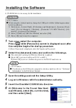
C A U T I O N
You will find a Recovery CD-ROM packet
in your accessories box. Please store the
packet in a safe place in case there is a
need to re-install your operating system
and/or application programs. (See Restoring
Your Pre-installed Software from the
Recovery CD-ROM on pages 160.
)
How do I register?
For Windows NT, you can register your system
on-line through our website by clicking the
LifeBook Registration icon on your desktop.
You must have access to the internet through
an Internet Service Provider to use this option.
Complete the electronic form and click on the
“send registration” button. Your registration
information will be transmitted to the Fujitsu
Registration Center and you will receive regis-
tration confirmation in one week to 10 days.
For Windows 98, you can access the
E-Registration program by selecting the
Register Now option in the Welcome to
Windows 98 wizard menu. This menu appears
the first time you start Windows 98 after com-
pleting the Condition of Use process. To access
the Welcome to Windows 98 wizard anytime,
double-click on the Welcome to Windows 98
icon on your desktop. You can send your regis-
tration through modem or Ethernet line.
You may also fill out the registration form that
is included on the keyboard and fax it to
1-949-450-9140 or mail it to:
Fujitsu PC Corporation
15355 Barranca Pkwy, Irvine, CA 92618-9520
Alternately you may call:
1-800-8fujitsu (1-800-838-5487)
REGISTERING YOUR LIFEBOOK
What are the benefits of registering?
You will receive an identification label for your
LifeBook, which, if your LifeBook is ever lost,
may help in getting it returned to you. You also
receive priority Personal Identification Number
(PIN) technical support access and useful prod-
uct mailings. Proof of purchase is not required
if you register within 30 days of your purchase.
P O I N T
You can register your LifeBook L Series
notebook with any operating system via
e-mail, telephone or fax.
P O I N T
Make sure you have connected a phone
line to your modem before you use
E-Registration.
Summary of Contents for Lifebook L470
Page 6: ...Black White of Cover to come ...
Page 7: ...T a b l e o f C o n t e n t s ...
Page 10: ...T a b l e o f C o n t e n t s iv ...
Page 11: ...LifeBook L Series from Fujitsu P r e f a c e ...
Page 14: ...P r e f a c e viii ...
Page 26: ...S e c t i o n O n e 12 ...
Page 70: ...S e c t i o n T h r e e 56 ...
Page 130: ...S e c t i o n F o u r 116 ...
Page 150: ...S e c t i o n F i v e 136 ...
Page 182: ...S e c t i o n S e v e n 168 ...
Page 196: ...A p p e n d i c e s 182 ...
Page 197: ...I n d e x ...