


En-2
2.3. Accessories
WARNING
For installation purposes, be sure to use the parts supplied by the manufacturer or other
prescribed parts. The use of non-prescribed parts can cause serious accidents such as
the unit falling, water leakage, electric shock, or
fi
re.
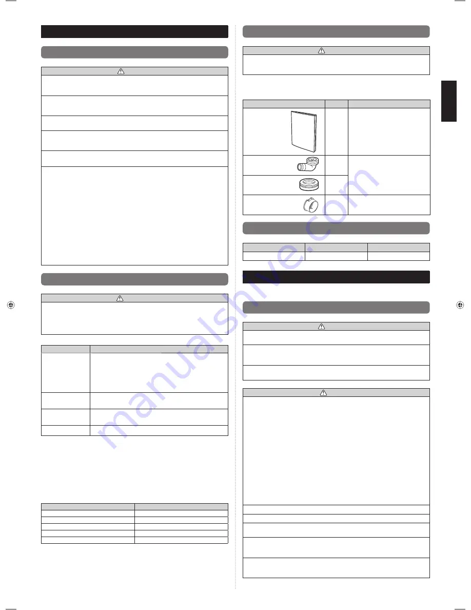
Following installation parts are supplied. Use them as required.
Keep this manual in a safe place, and do not discard any other accessories until the
installation work has been completed.
Name and shape
Q’ty
Description
Installation
manual
1
This manual
Drain pipe
1
For outdoor unit drain piping work
(May not be supplied, depending on
the model.)
Drain cap
2
One-touch bush
2
For power supply cable and
connection cable installation
2.4. Operating range
Outdoor
Cooling/Dry Mode
Heating Mode
Temperature
About -15 °C to 46 °C
About -15 °C to 24 °C
3. INSTALLATION WORK
Make sure to obtain the customer’s approval for selecting and installing the outdoor unit.
3.1. Selecting an installation location
WARNING
Securely install the outdoor unit at a location that can withstand the weight of the unit.
Otherwise, the outdoor unit may fall and cause injury.
Be sure to install the outdoor unit as prescribed, so that it can withstand earthquakes
and typhoons or other strong winds. Improper installation can cause the unit to topple or
fall, or other accidents.
Do not install the outdoor unit near the edge of a balcony. Otherwise, children may climb
onto the outdoor unit and fall off of the balcony.
CAUTION
Do not install the outdoor unit in the following areas:
Area with high salt content, such as at the seaside. It will deteriorate metal parts,
•
causing the parts to fail or the unit to leak water.
Area
fi
lled with mineral oil or containing a large amount of splashed oil or steam,
•
such as a kitchen. It will deteriorate plastic parts, causing the parts to fail or the unit
to leak water.
Area that generates substances that adversely affect the equipment, such as sulfuric
•
gas, chlorine gas, acid, or alkali. It will cause the copper pipes and brazed joints to
corrode, which can cause refrigerant leakage.
Area containing equipment that generates electromagnetic interference. It will cause
•
the control system to malfunction, preventing the unit from operating normally.
Area that can cause combustible gas to leak, contains suspended carbon
fi
bers or
•
fl
ammable dust, or volatile in
fl
ammables such as paint thinner or gasoline. If gas
leaks and settles around the unit, it can cause a
fi
re.
Area where small animals may live. It may cause failure, smoke or
fi
re if small
•
animals enter and touch internal electrical parts.
Area where animals may urinate on the unit or ammonia may be generated.
•
Do not tilt the outdoor unit more than 3 degrees.
Install the outdoor unit in a well-ventilated location away from rain or direct sunlight.
If the outdoor unit must be installed in an area within easy reach of the general public,
install as necessary a protective fence or the like to prevent their access.
Install the outdoor unit in a location that would not inconvenience your neighbors, as
they could be affected by the air
fl
ow coming out from the outlet, noise, or vibration. If it
must be installed in proximity to your neighbors, be sure to obtain their approval.
If the outdoor unit is installed in a cold region that is affected by snow accumulation,
snow fall, or freezing, take appropriate measures to protect it from those elements.
To ensure a stable operation, install inlet and outlet ducts.
2. ABOUT THE UNIT
d
2.1. Precautions for using R410A refrigerant
WARNING
Do not introduce any substance other than the prescribed refrigerant into the
refrigeration cycle. If air enters the refrigeration cycle, the pressure in the refrigeration
cycle will become abnormally high and cause the piping to rupture.
If there is a refrigerant leak, make sure that it does not exceed the concentration limit.
If a refrigerant leak exceeds the concentration limit, it can lead to accidents such as
oxygen starvation.
Do not touch refrigerant that has leaked from the refrigerant pipe connections or other
areas. Touching the refrigerant directly can cause frostbite.
If a refrigerant leak occurs during operation, immediately vacate the premises and
thoroughly ventilate the area. If the refrigerant comes in contact with a
fl
ame, it produces
a toxic gas.
The basic installation work procedures are the same as conventional refrigerant models.
However, pay careful attention to the following points:
Since the working pressure is 1.6 times higher than that of conventional refrigerant
•
(R22) models, some of the piping and installation and service tools are special. (See
the table below.)
Especially, when replacing a conventional refrigerant (R22) model with a new
refrigerant R410A model, always replace the conventional piping and
fl
are nuts with
the R410A piping and
fl
are nuts.
Models that use refrigerant R410A have a different charging port thread diameter
•
to prevent erroneous charging with conventional refrigerant (R22) and for safety.
Therefore, check beforehand. [The charging port thread diameter for R410A is 1/2
UNF 20 threads per inch.]
Be careful that foreign matter (oil, water, etc.) does not enter the piping than with
•
refrigerant models. Also, when storing the piping, securely seal the openings by
pinching, taping, etc.
When charging the refrigerant, take into account the slight change in the composition
•
of the gas and liquid phases. And always charge from the liquid phase where
refrigerant composition is stable.
2.2. Special tools for R410A
WARNING
To install a unit that uses R410A refrigerant, use dedicated tools and piping materials
that have been manufactured speci
fi
cally for R410A use. Because the pressure of
R410A refrigerant is approximately 1.6 times higher than R22, failure to use dedicated
piping material or improper installation can cause rupture or injury. Furthermore, it can
cause serious accidents such as water leakage, electric shock, or
fi
re.
Tool name
Changes
Gauge manifold
Pressure is high and cannot be measured with a conventional
gauge. To prevent erroneous mixing of other refrigerants, the
diameter of each port has been changed.
It is recommended the gauge with seals –0.1 to 5.3 MPa (-1 to
53 bar) for high pressure. –0.1 to 3.8 MPa (-1 to 38 bar) for low
pressure.
Charging hose
To increase pressure resistance, the hose material and base
size were changed.
Vacuum pump
A conventional vacuum pump can be used by installing a
vacuum pump adapter.
Gas leakage detector Special gas leakage detector for HFC refrigerant R410A.
Copper pipes
It is necessary to use seamless copper pipes and it is desirable that the amount of residual
oil is less than 40 mg/10 m. Do not use copper pipes having a collapsed, deformed or
discolored portion (especially on the interior surface). Otherwise, the expansion valve or
capillary tube may become blocked with contaminants.
As an air conditioner using R410A incurs pressure higher than when using conventional
refrigerant, it is necessary to choose adequate materials.
Thicknesses of copper pipes used with R410A are as shown in the table. Never use
copper pipes thinner than that in the table even when it is available on the market.
Thicknesses of Annealed Copper Pipes (R410A)
Pipe outside diameter [mm (in.)]
Thickness [mm]
6.35 (1/4)
0.80
9.52 (3/8)
0.80
12.70 (1/2)
0.80
15.88 (5/8)
1.00
19.05 (3/4)
1.20
9379069403_IM.indb 2
9379069403_IM.indb 2
1/29/2013 4:44:18 PM
1/29/2013 4:44:18 PM


