En-9
6.4. Wiring method
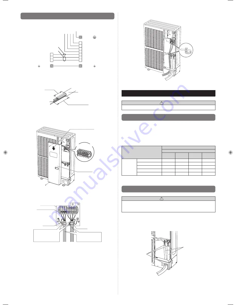
6.4.1. Connection diagrams
POWER SUPPLY
Indoor unit
side terminal
Outdoor unit
side terminal
N
L3
L2
L1
3
3
2
2
1
1
N
(T)
(S)
(R)
EARTH
(GROUND)
EARTH
(GROUND)
EARTH
(GROUND)
Earthing (Grounding) line
Power line
Control line
6.4.2. Connection cable preparation
Keep the earth (ground) wire longer than the other wires.
Earth (Ground) wire
40 mm
Power supply cable or
Transmission cable
60 mm or more
6.4.3. Wiring procedure
(1) Remove the service panel cover, insulation sheet and connect the wires to the
terminal in accordance with the terminal nameplate. (Fig. A, Fig. B)
Fig.
A
Direction of the service
panel removal
Terminal blocks
Service panel
(2) After connecting the wires, use cable clips to secure the wires. (Fig. B)
Connect the wires without applying excessive tension.
•
Fig.
B
Control box
Terminal blocks
Cable clip
Cable clip
Firmly secure the
cable clips so that the
wire terminals will not
receive external stress.
Use the speci
fi
ed wire
type and connect the
wires securely.
(3) Secure the cables using the cable clips under the terminal blocks, and then secure
the cables using the cable clips attached to the base of the valves.
Cable clip
(4) Be sure to install the insulation sheet after the wiring is complete.
s
d
7. PIPE INSTALLATION-2
WARNING
Install the insulated pipes so that they do not touch the compressor.
7.1. Installing insulation
Use an insulation on the refrigerant pipes to prevent condensation and dripping.
•
(Fig. A)
Determine the thickness of the insulation material by referring to Table A.
•
Table A, Selection of insulation
(for using an insulation material with equal heat transmission rate or below
0.040 W/(m·k))
Relative humidity
[mm (in.)]
Insulation material
Minimum thickness [mm]
70%
or more
75%
or more
80%
or more
85%
or more
Pipe
diameter
6.35 (1/4)
8
10
13
17
9.52 (3/8)
9
11
14
18
12.70 (1/2)
10
12
15
19
15.88 (5/8)
10
12
16
20
19.05 (3/4)
10
13
16
21
If the ambient temperature and relative humidity exceed 32 °C, increase the level of heat
insulation for the refrigerant pipes.
7.2. Filling with putty
WARNING
Fill the piping holes with putty (supplied locally) to avoid any gap (Fig. A). If small
animals such as insects enter the external unit, a short circuit may be caused near
electrical components in the service panel.
If the outdoor unit is installed at a level that is higher than the indoor unit, the water that
has condensed in the 3-way valve of the outdoor unit could travel to the indoor unit.
Therefore, use putty in the space between the pipe and the insulation to prevent the entry
of water.
Fig. A
Insulation
Putty
9379069403_IM.indb 9
9379069403_IM.indb 9
1/29/2013 4:44:20 PM
1/29/2013 4:44:20 PM


