


En-5
BENDING PIPES
(1) When bending the pipe, be careful not to crush it.
(2) To prevent breaking of the pipe, avoid sharp bends.
Bend the pipe with a radius of curvature of 70 mm or over.
(3) If the copper pipe is bend the pipe or pulled to often, it will become stiff. Do not
bend the pipes more than three times at one place.
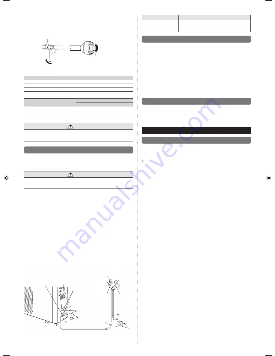
Holding spanner
90°
Body side
Torque wrench
To prevent gas leakage, coat the
fl
are
surface with refrigerator oil.
Table 1
Flare nut tightening torque
Flare nut [mm (in.)]
Tightening torque [N•m (kgf•cm)]
6.35 (1/4) dia.
16 to 18 (160 to 180)
12.70 (1/2) dia.
49 to 61 (490 to 610)
15.88 (5/8) dia.
63 to 75 (630 to 750)
Table 2
Pipe outside diameter
Pipe outside diameter
[mm (in.)]
Dimension A [mm]
Flare tool for R410A, clutch type
6.35 (1/4)
0 to 0.5
12.70 (1/2)
15.88 (5/8)
CAUTION
Fasten a
fl
are nut with a torque wrench as instructed in this manual. If fastened too
tight, the
fl
are nut may be broken after a long period of time and cause a leakage of
refrigerant.
5.6. Air purge
Always use a vacuum pump to purge the air.
Refrigerant for purging the air is not charged in the outdoor unit at the factory.
Close the high pressure side valve of the gauge manifold fully and do not operate it during
the following work.
CAUTION
Refrigerant must not be discharged into atmosphere.
After connecting the piping , check the joints for gas leakage with gas leak detector.
(1) Check if the piping connections are secure.
(2) Check that the stems of 2-way valve and 3-way valve are closed fully.
(3) Connect the gauge manifold charge hose to the charging port of the 3-way valve (side
with the projection for pushing in the valve core).
(4) Open the low pressure side valve of the gauge manifold fully.
(5) Operate the vacuum pump and start pump down.
(6) Slowly loosen the
fl
are nut of the 3-way valve and check if air enters, then retighten
the
fl
are nut.
(When the
fl
are nut is loosened the operating sound of the vacuum pump changes
and the reading of the compound pressure gauge goes from minus to zero.)
(7) Pump down the system for at least 15 minutes, then check if the compound pressure
gauge reads -0.1 MPa (-76 cmHg, -1 bar).
(8) At the end of pump down, close the low pressure side gauge of the gauge manifold
fully and stop the vacuum pump.
(9) Slowly loosen the valve stem of the 3-way valve. When the compound pressure
gauge reading reaches 0.1-0.2 MPa, retighten the valve stem and disconnect the
charge hose from the 3-way valve charging port.
(If the stem of the 3-way valve is opened fully before the charge hose is disconnect-
ed, it may be dif
fi
cult to disconnect the charge hose.)
(10) Fully open the valve stems of the 2-way valve and 3-way valve using a hexagon
wrench. (After the valve stem begins to turn, turn it with a torque of less than
2.9 N • m (30 kgf • cm) until it stops turning.)
(11) Firmly tighten the 2-way valve and 3-way valve blank cap and the charging port cap.
3-way valve
2
-way valve
Charging
port cap
Vacuum pump
Charge
hose
Charge hose
Charging port
Blank cap
Valve stem
Flare nut
Compound pressure gauge
Gauge manifold
Pressure gauge
High
pressure
side valve
(closed)
Low
pressure
side
valve
-0.1 MPa
(-76 cmHg
-1 bar)
Tightening torque
Blank cap (2-way valve)
20.0 to 25.0 N • m (200 to 250 kgf • cm)
Blank cap (3-way valve)
28.0 to 32.0 N • m (280 to 320 kgf • cm)
Charging port cap
12.5 to 16.0 N • m (125 to 160 kgf • cm)
5.7. Test run
1. Make a TEST RUN in accordance with installation manual for the indoor
unit.
CHECK ITEMS
INDOOR UNIT
For check items refer to the installation manual for the indoor unit.
OUTDOOR UNIT
(1) Is there any abnormal noise and vibration during operation?
(2) Will noise, wind, or drain water from the unit disturb the neighbors?
(3) Is there any gas leakage?
• Do not operate the air conditioner in the test running state for a long time.
• For the operation method, refer to the operating manual and perform operation check.
5.8. Customer guidance
Explain the followings to the customer in accordance with the operating manual:
(1) Starting and stopping method, operation switching, temperature adjustment, timer,
air
fl
ow switching, and other remote controller operations.
(2) Air
fi
lter removal and cleaning, and how to use the air
fl
ow direction louvers.
(3) Give the operating and installation manuals to the customer.
6. PUMP DOWN
6.1. Pump down
PUMP DOWN OPERATION
To avoid discharging refrigerant into the atmosphere at the time of relocation or disposal,
recover refrigerant by doing the test run operation according to the following procedure.
(1) Conduct preliminary operation for 5 to 10 minutes using the test run operation.
For test run operation refer to the installation manual for the indoor unit.
(2) Close the valve stem of 2-way valve completely.
(3) Continue the test run operation for 2 to 3 minutes, then close all the valve stems on
the 3-way valves.
(4) Stop the operation.
• Press the START/STOP button of the remote controller to stop the operation.
9332809107-02_IM.indb 5
9332809107-02_IM.indb 5
11/27/2015 3:03:52 PM
11/27/2015 3:03:52 PM


